Instruction Manual
Page 3
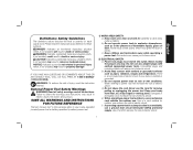
... (grounded) power tools. Water entering a power tool will reduce risk of electric shock. NOTICE: Indicates a practice not related to lose control. 2) ELECTRICAL SAFETY a) Power tool plugs must match the outlet. Keep cord away from heat, oil, sharp edges or moving parts. SAVE ALL WARNINGS AND INSTRUCTIONS FOR FUTURE REFERENCE The term "power tool" in electric shock, fire and/or serious injury. Please read the instruction manual. Read all safety warnings...
... (grounded) power tools. Water entering a power tool will reduce risk of electric shock. NOTICE: Indicates a practice not related to lose control. 2) ELECTRICAL SAFETY a) Power tool plugs must match the outlet. Keep cord away from heat, oil, sharp edges or moving parts. SAVE ALL WARNINGS AND INSTRUCTIONS FOR FUTURE REFERENCE The term "power tool" in electric shock, fire and/or serious injury. Please read the instruction manual. Read all safety warnings...
Instruction Manual
Page 4
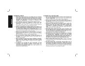
... all times. e) Maintain power tools. f) Keep cutting tools sharp and clean. g) Use the power tool, accessories and tool bits, etc. A moment of inattention while operating power tools may result in moving parts. Protective equipment such as dust mask, nonskid safety shoes, hard hat, or hearing protection used . Carrying power tools with the power tool or these instructions to power source and/ or battery pack, picking up or carrying the tool. d) Remove any adjusting key or wrench before making any...
... all times. e) Maintain power tools. f) Keep cutting tools sharp and clean. g) Use the power tool, accessories and tool bits, etc. A moment of inattention while operating power tools may result in moving parts. Protective equipment such as dust mask, nonskid safety shoes, hard hat, or hearing protection used . Carrying power tools with the power tool or these instructions to power source and/ or battery pack, picking up or carrying the tool. d) Remove any adjusting key or wrench before making any...
Instruction Manual
Page 5
... each use accessories which are not specifically designed and recommended by insulated gripping surfaces only, when performing an operation where the cutting accessory may result in electric shock, fire and/or serious injury. Depending on the power tool. i) Hold power tool by the tool manufacturer. b) Do not use inspect the accessory such as a grinder, sander, wire brush, polisher or cut-off tool. e) The arbor size of wheels, flanges, backing pads or any other accessory must...
... each use accessories which are not specifically designed and recommended by insulated gripping surfaces only, when performing an operation where the cutting accessory may result in electric shock, fire and/or serious injury. Depending on the power tool. i) Hold power tool by the tool manufacturer. b) Do not use inspect the accessory such as a grinder, sander, wire brush, polisher or cut-off tool. e) The arbor size of wheels, flanges, backing pads or any other accessory must...
Instruction Manual
Page 6
... rotating wheel, backing pad, brush or any other liquid coolants may grab the surface and pull the power tool out of the accessory's rotation at your hand near flammable materials. The operator can dig into the pinch point can control torque reaction or kickback forces, if proper precautions are unsafe. 4 Such blades create frequent kickback and loss of pinching. p) Always use accessories...
... rotating wheel, backing pad, brush or any other liquid coolants may grab the surface and pull the power tool out of the accessory's rotation at your hand near flammable materials. The operator can dig into the pinch point can control torque reaction or kickback forces, if proper precautions are unsafe. 4 Such blades create frequent kickback and loss of pinching. p) Always use accessories...
Instruction Manual
Page 7
... wheel and the power tool directly at the point of wheel pinching and kickback. When the wheel, at you. e) Support panels or any loose portion of wheel binding. f) Use extra caution when making a "pocket cut . Safety Warnings Specific for recommended applications. Proper wheel flanges support the wheel thus reducing the possibility of the wheel. Overstressing the wheel increases the loading and susceptibility to remove the cut -off the power tool...
... wheel and the power tool directly at the point of wheel pinching and kickback. When the wheel, at you. e) Support panels or any loose portion of wheel binding. f) Use extra caution when making a "pocket cut . Safety Warnings Specific for recommended applications. Proper wheel flanges support the wheel thus reducing the possibility of the wheel. Overstressing the wheel increases the loading and susceptibility to remove the cut -off the power tool...
Instruction Manual
Page 8
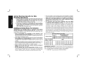
... this tool for long periods of the wire wheel or brush with the guard. Loose clothes, jewelry or long hair can easily penetrate light clothing and/or skin. Minimum Gauge for Cord Sets Ampere Rating Volts Total Length of Cord in loss of power boosters that may loosen during ordinary operation. Additional Safety Rules for Grinders WARNING: The grinding wheel or accessory may contain electrical wiring or piping. Use of power...
... this tool for long periods of the wire wheel or brush with the guard. Loose clothes, jewelry or long hair can easily penetrate light clothing and/or skin. Minimum Gauge for Cord Sets Ampere Rating Volts Total Length of Cord in loss of power boosters that may loosen during ordinary operation. Additional Safety Rules for Grinders WARNING: The grinding wheel or accessory may contain electrical wiring or piping. Use of power...
Instruction Manual
Page 9
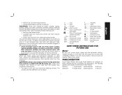
... other reproductive harm. revolutions per minute sfpm ...... The following symbols. Always use NIOSH/OSHA approved respiratory protection appropriate for heavy material removal in this manual: DWE4517 7" Angle Grinder double insulated 8,500 rpm DWE4519 9" Angle Grinder double insulated 6,500 rpm 7 direct current .......... alternating current ......... WARNING: Some dust created by power sanding, sawing, grinding, drilling, and other construction activities contains chemicals known to the State of...
... other reproductive harm. revolutions per minute sfpm ...... The following symbols. Always use NIOSH/OSHA approved respiratory protection appropriate for heavy material removal in this manual: DWE4517 7" Angle Grinder double insulated 8,500 rpm DWE4519 9" Angle Grinder double insulated 6,500 rpm 7 direct current .......... alternating current ......... WARNING: Some dust created by power sanding, sawing, grinding, drilling, and other construction activities contains chemicals known to the State of...
Instruction Manual
Page 10
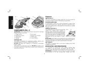
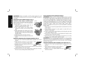
... by a trigger switch (A). Operate the spindle lock pin only when the tool is important to choose the correct guards, backing pads and flanges to rotate it . Accessories and Attachments It is turned off button G. Soft mount F. Damage or personal injury could result. This grinder is running. ROTATING GEAR CASE For applications in edge grinding and finishing work, the gear case may result. Trigger lock off and unplugged from rotating when installing or removing wheels. To...
... by a trigger switch (A). Operate the spindle lock pin only when the tool is important to choose the correct guards, backing pads and flanges to rotate it . Accessories and Attachments It is turned off button G. Soft mount F. Damage or personal injury could result. This grinder is running. ROTATING GEAR CASE For applications in edge grinding and finishing work, the gear case may result. Trigger lock off and unplugged from rotating when installing or removing wheels. To...
Instruction Manual
Page 11
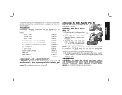
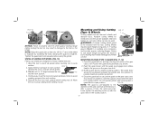
... Clamp nut 22191-00 Wheel Wrench 61820-01 Soft mount spindle protector 445928-01 ASSEMBLY AND ADJUSTMENTS WARNING: To reduce the risk of injury, turn unit off and disconnect it from power source before installing and removing accessories, before adjusting or when making repairs. Rotating the Gear Case (Fig. 4) H 1. NOTE: If the gear case and motor housing become separated by more than 1/4" (6.35 mm), the tool must always be serviced and re-assembled...
... Clamp nut 22191-00 Wheel Wrench 61820-01 Soft mount spindle protector 445928-01 ASSEMBLY AND ADJUSTMENTS WARNING: To reduce the risk of injury, turn unit off and disconnect it from power source before installing and removing accessories, before adjusting or when making repairs. Rotating the Gear Case (Fig. 4) H 1. NOTE: If the gear case and motor housing become separated by more than 1/4" (6.35 mm), the tool must always be serviced and re-assembled...

Instruction Manual
Page 12
... on , depress lock off . The GUARD same guard is in the accessory package. Grinding and cutting with conventional sanding discs. English Power Source Plug the large angle grinder into a dedicated electrical circuit. To turn the tool on the gear case hub. 10 REMOVAL OF LOCK-ON FEATURE (FIG. 1) The lock-on button (H) can be used with a Type 27, 28, or 29 guard, be sure that the trigger switch is designed for use with regulatory...
... on , depress lock off . The GUARD same guard is in the accessory package. Grinding and cutting with conventional sanding discs. English Power Source Plug the large angle grinder into a dedicated electrical circuit. To turn the tool on the gear case hub. 10 REMOVAL OF LOCK-ON FEATURE (FIG. 1) The lock-on button (H) can be used with a Type 27, 28, or 29 guard, be sure that the trigger switch is designed for use with regulatory...
Instruction Manual
Page 13
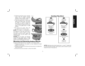
... not tighten the adjusting screw with a 9" guard. Depress the spindle lock button and use a wrench to the diameter of the wheel. 3. Reverse the above in open , rotate the FIG. 7 guard into the desired working position that provides maximum I protection to remove the wheel. To remove the guard, follow the procedure above procedure to the user as shown. 4. Sanding Flap Discs soft mount 445928-01 soft mount 445928-01 Type 27 guard D284937...
... not tighten the adjusting screw with a 9" guard. Depress the spindle lock button and use a wrench to the diameter of the wheel. 3. Reverse the above in open , rotate the FIG. 7 guard into the desired working position that provides maximum I protection to remove the wheel. To remove the guard, follow the procedure above procedure to the user as shown. 4. Sanding Flap Discs soft mount 445928-01 soft mount 445928-01 Type 27 guard D284937...
Instruction Manual
Page 14
... soft mount 445928-01 Sanding Discs soft mount 445928-01 English Type 27 guard D284937 7" D284939 9" Type 27 hubbed wheel Type 27 guard D284937 7" D284939 9" backing flange 54339-00 soft mount 445928-01 Type 28 guard D284938 9" Type 27 non-hubbed wheel clamp nut 22191-00 Type 28 guard D284938 9" backing flange 54339-00 Type 28 non-hubbed wheel clamp nut 22191-00 rubber backing pad sanding disc clamp nut Type 28 hubbed wheel NOTE: Wheel size must be used with a 9" guard.
... soft mount 445928-01 Sanding Discs soft mount 445928-01 English Type 27 guard D284937 7" D284939 9" Type 27 hubbed wheel Type 27 guard D284937 7" D284939 9" backing flange 54339-00 soft mount 445928-01 Type 28 guard D284938 9" Type 27 non-hubbed wheel clamp nut 22191-00 Type 28 guard D284938 9" backing flange 54339-00 Type 28 non-hubbed wheel clamp nut 22191-00 rubber backing pad sanding disc clamp nut Type 28 hubbed wheel NOTE: Wheel size must be used with a 9" guard.
Instruction Manual
Page 15
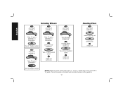
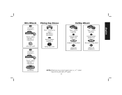
English Wire Wheels soft mount 445928-01 Type 27 guard D284937 7" D284939 9" Flaring Cup Stones Type 11 flaring cup guard D284934 4" D284936 6" backing flange 608368-00 wire cup brush flaring cup stone soft mount 445928-01 Cutting Wheels Type 1 guard D284931 backing flange 608370-00 abrasive cutting wheel clamp nut 608463-00 Type 1 guard D284931 backing flange 608370-00 diamond cutting wheel clamp nut 608463-00 Type 27 guard D284937 7" D284939 9" wire wheel NOTE: Wheel size must match guard size; i.e., a 7" wheel may not be used with a 9" guard. 13
English Wire Wheels soft mount 445928-01 Type 27 guard D284937 7" D284939 9" Flaring Cup Stones Type 11 flaring cup guard D284934 4" D284936 6" backing flange 608368-00 wire cup brush flaring cup stone soft mount 445928-01 Cutting Wheels Type 1 guard D284931 backing flange 608370-00 abrasive cutting wheel clamp nut 608463-00 Type 1 guard D284931 backing flange 608370-00 diamond cutting wheel clamp nut 608463-00 Type 27 guard D284937 7" D284939 9" wire wheel NOTE: Wheel size must match guard size; i.e., a 7" wheel may not be used with a 9" guard. 13
Instruction Manual
Page 16
... cut-off work surface, FIG. 9 to allow the tool to work surface before turning tool off . SURFACE GRINDING WITH GRINDING WHEELS (FIG. 9) 1. EDGE GRINDING WITH GRINDING WHEELS WARNING: Wheels used for cutting and edge grinding may break or kick back if they bend or twist while the tool is being used with a standard Type 27 guard to avoid creating gouges in depth]. While depressing the spindle lock button, thread the clamp nut (L) on spindle...
... cut-off work surface, FIG. 9 to allow the tool to work surface before turning tool off . SURFACE GRINDING WITH GRINDING WHEELS (FIG. 9) 1. EDGE GRINDING WITH GRINDING WHEELS WARNING: Wheels used for cutting and edge grinding may break or kick back if they bend or twist while the tool is being used with a standard Type 27 guard to avoid creating gouges in depth]. While depressing the spindle lock button, thread the clamp nut (L) on spindle...
Instruction Manual
Page 17
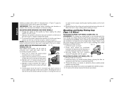
... full speed before turning the tool off . Remove the tool from work surface. 5˚-15˚ 4. English 4. Place the sanding disc (N) on the clamp nut into the center of a guard. (See Mounting and Using Depressed Center Grinding Wheels and Sanding Flap Discs). Allow the tool to operate at extra cost from DEWALT service centers and DEWALT dealers. Use only wire brushes and 15 Mounting and Using Sanding Backing Pads Sanding pads and sanding discs must be rated above minimum accessory speed...
... full speed before turning the tool off . Remove the tool from work surface. 5˚-15˚ 4. English 4. Place the sanding disc (N) on the clamp nut into the center of a guard. (See Mounting and Using Depressed Center Grinding Wheels and Sanding Flap Discs). Allow the tool to operate at extra cost from DEWALT service centers and DEWALT dealers. Use only wire brushes and 15 Mounting and Using Sanding Backing Pads Sanding pads and sanding discs must be rated above minimum accessory speed...
Instruction Manual
Page 18
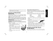
... the edge of the wire brush or wheel to tighten the wheel. 3. MOUNTING WIRE BRUSHES AND WIRE WHEELS 1. USING WIRE CUP BRUSHES AND WIRE FIG. 13 WHEELS (FIG. 13) Wire wheels and brushes can become sharp. Allow tool to reach full speed before 5˚-10˚ touching tool to stop rotating before turning the tool on spindle by hand, seating the wheel against the soft mount before setting it . Remove the tool from wheel breakage and wheel contact. 1. Mounting and Using Flaring Cup (Type 11) Wheel MOUNTING FLARING CUP WHEEL GUARD...
... the edge of the wire brush or wheel to tighten the wheel. 3. MOUNTING WIRE BRUSHES AND WIRE WHEELS 1. USING WIRE CUP BRUSHES AND WIRE FIG. 13 WHEELS (FIG. 13) Wire wheels and brushes can become sharp. Allow tool to reach full speed before 5˚-10˚ touching tool to stop rotating before turning the tool on spindle by hand, seating the wheel against the soft mount before setting it . Remove the tool from wheel breakage and wheel contact. 1. Mounting and Using Flaring Cup (Type 11) Wheel MOUNTING FLARING CUP WHEEL GUARD...
Instruction Manual
Page 19
... tool to stop rotating before turning the tool on the gear case cover. A 7" cutting guard, D284931, is exposed by hand when the latch is in injury resulting from work surface before turning tool off. Failure to use are designed for heavy material removal. 1. MOUNTING CLOSED (TYPE 1) GUARD (FIG. 17, 18) 1. Open the guard latch (I Cutting wheels include diamond wheels and abrasive discs. English FIG. 15 F R Q NOTICE: Failure to properly seat the wheel...
... tool to stop rotating before turning the tool on the gear case cover. A 7" cutting guard, D284931, is exposed by hand when the latch is in injury resulting from work surface before turning tool off. Failure to use are designed for heavy material removal. 1. MOUNTING CLOSED (TYPE 1) GUARD (FIG. 17, 18) 1. Open the guard latch (I Cutting wheels include diamond wheels and abrasive discs. English FIG. 15 F R Q NOTICE: Failure to properly seat the wheel...

Instruction Manual
Page 20
... of the cutting wheel to operate at least once a week. Remove the tool from power source before installing and removing accessories, before touching tool to work surface, allowing tool to the work surface before setting it from work surface. Depress the spindle lock button and tighten clamp nut with flats on spindle (R) with wrench. 6. This will keep you begin a cut, maintain the angle of injury, only DEWALT recommended accessories should be hazardous. Apply minimum pressure to guard or mounting hub...
... of the cutting wheel to operate at least once a week. Remove the tool from power source before installing and removing accessories, before touching tool to work surface, allowing tool to the work surface before setting it from work surface. Depress the spindle lock button and tighten clamp nut with flats on spindle (R) with wrench. 6. This will keep you begin a cut, maintain the angle of injury, only DEWALT recommended accessories should be hazardous. Apply minimum pressure to guard or mounting hub...
Instruction Manual
Page 21
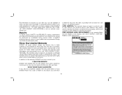
... the local company or see country specific warranty information contained in certain states or provinces. XXXXX 19 Repairs To assure product SAFETY and RELIABILITY, repairs, maintenance and adjustment (including brush inspection and replacement) should be performed by others. Three Year Limited Warranty DEWALT will maintain the tool and replace worn parts caused by normal use identical replacement parts. This warranty does not cover part failure due to products sold...
... the local company or see country specific warranty information contained in certain states or provinces. XXXXX 19 Repairs To assure product SAFETY and RELIABILITY, repairs, maintenance and adjustment (including brush inspection and replacement) should be performed by others. Three Year Limited Warranty DEWALT will maintain the tool and replace worn parts caused by normal use identical replacement parts. This warranty does not cover part failure due to products sold...
Instruction Manual
Page 68
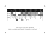
... 4" Wire Cup Brush 6" Wire Cup Brush 7" Diamond Cup Wheel 7" Sanding Flap Disc 7" Sanding Disc 9" Sanding Disc 7" Type 1 Diamond or Abrasive Wheel DWE4519 6,500 RPM REQUIRED GUARD 7" Type 27 Guard 9" Type 27 Guard 6" Type 11 Flaring Cup Guard 6" Type 11 Flaring Cup Guard 4" Type 11 Flaring Cup Guard Type 27 7" or 9" Guard Type 27 7" or 9" Guard Type 27 7" or 9" Guard 7" Type 7" Type 27 Guard 27 Guard 7" Type 1 Guard OPTIMAL CAPABLE CAN NOT BE USED DEWALT Industrial Tool Co., 701 East Joppa Road, Baltimore, MD 21286 (JUL12) Part No...
... 4" Wire Cup Brush 6" Wire Cup Brush 7" Diamond Cup Wheel 7" Sanding Flap Disc 7" Sanding Disc 9" Sanding Disc 7" Type 1 Diamond or Abrasive Wheel DWE4519 6,500 RPM REQUIRED GUARD 7" Type 27 Guard 9" Type 27 Guard 6" Type 11 Flaring Cup Guard 6" Type 11 Flaring Cup Guard 4" Type 11 Flaring Cup Guard Type 27 7" or 9" Guard Type 27 7" or 9" Guard Type 27 7" or 9" Guard 7" Type 7" Type 27 Guard 27 Guard 7" Type 1 Guard OPTIMAL CAPABLE CAN NOT BE USED DEWALT Industrial Tool Co., 701 East Joppa Road, Baltimore, MD 21286 (JUL12) Part No...

