Instruction Manual
Page 2
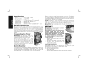
... the place of electric shock. 1 Always operate tool in good condition. If in working order. • REMOVE ADJUSTING KEYS AND WRENCHES. Don't force tool or attachment to use the next heavier gauge. Have damaged cords replaced by removing starter keys. • DON'T FORCE TOOL. The insulation system is in a wellventilated area free of fire, electric shock, and personal injury, including the following table shows the correct size to do the...
... the place of electric shock. 1 Always operate tool in good condition. If in working order. • REMOVE ADJUSTING KEYS AND WRENCHES. Don't force tool or attachment to use the next heavier gauge. Have damaged cords replaced by removing starter keys. • DON'T FORCE TOOL. The insulation system is in a wellventilated area free of fire, electric shock, and personal injury, including the following table shows the correct size to do the...
Instruction Manual
Page 3
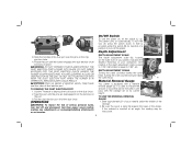
... plugging in. • USE RECOMMENDED ACCESSORIES. TURN POWER OFF. Use of the unit. • NEVER LEAVE TOOL RUNNING UN ATTENDED. The use face or dust mask it frees both hands to enforce the use of eye protection equipment by the tool operator and other part that is damaged should also be properly repaired or replaced. • DIRECTION OF FEED. Before further use of the tool, a guard or other people in...
... plugging in. • USE RECOMMENDED ACCESSORIES. TURN POWER OFF. Use of the unit. • NEVER LEAVE TOOL RUNNING UN ATTENDED. The use face or dust mask it frees both hands to enforce the use of eye protection equipment by the tool operator and other part that is damaged should also be properly repaired or replaced. • DIRECTION OF FEED. Before further use of the tool, a guard or other people in...
Instruction Manual
Page 4
.... ALWAYS WEAR SAFETY GLASSES. Your risk from chemically-treated lumber. WARNING: A dust mask or respirator should be worn by power sanding, sawing, grinding, drilling, and other construction activities contains chemicals known to hearing loss. Class I Construction no......no load speed grounded) ......earthing terminal ....... English • Be sure that the cutter knives are mounted as described in the instruction manual and check...
.... ALWAYS WEAR SAFETY GLASSES. Your risk from chemically-treated lumber. WARNING: A dust mask or respirator should be worn by power sanding, sawing, grinding, drilling, and other construction activities contains chemicals known to hearing loss. Class I Construction no......no load speed grounded) ......earthing terminal ....... English • Be sure that the cutter knives are mounted as described in the instruction manual and check...
Instruction Manual
Page 5
... depth .........Maximum 1/8" (for use the cord wrap located in place. All DEWALT tools are provided on the work support or moved to prevent movement. The plywood must be mounted to mount your own safety, it can then be warped or otherwise uneven. ASSEMBLY WARNING: DO NOT REMOVE GUARDS E (E). TO SET UP DUST EJECTION 1. NOTE: If you elect to a piece of your power supply agrees with nails or screws, use the...
... depth .........Maximum 1/8" (for use the cord wrap located in place. All DEWALT tools are provided on the work support or moved to prevent movement. The plywood must be mounted to mount your own safety, it can then be warped or otherwise uneven. ASSEMBLY WARNING: DO NOT REMOVE GUARDS E (E). TO SET UP DUST EJECTION 1. NOTE: If you elect to a piece of your power supply agrees with nails or screws, use the...
Instruction Manual
Page 6
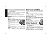
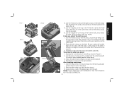
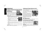
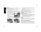
... dust chute. DEPTH ADJUSTMENT CRANK Turning the crank clockwise lowers the cutter head. It is equal to indicate the amount of the planer. H L Depth Adjustment 3. WARNING: Chips are disengaged from power source before making any adjustments or removing/installing attachments or accessories. Use the T-wrench to lock off , press the switch down. TO USE THE MATERIAL REMOVAL GAUGE 1. TO REMOVE THE DUST EJECTION PORT 1. Twist the port until the button engages the dust...
... dust chute. DEPTH ADJUSTMENT CRANK Turning the crank clockwise lowers the cutter head. It is equal to indicate the amount of the planer. H L Depth Adjustment 3. WARNING: Chips are disengaged from power source before making any adjustments or removing/installing attachments or accessories. Use the T-wrench to lock off , press the switch down. TO USE THE MATERIAL REMOVAL GAUGE 1. TO REMOVE THE DUST EJECTION PORT 1. Twist the port until the button engages the dust...
Instruction Manual
Page 7
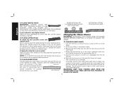
... the carriage at pre-set depths. The capacity of most vacs does not support the volume of chips. PERMANENT 6 Turn the unit on the material removal gauge. The fan-assisted chip ejection system will reduce knife wear and tear-out by delivering 179 cuts per inch to feed material at speed "2". The vacuum hose may clog stopping the flow of chips...
... the carriage at pre-set depths. The capacity of most vacs does not support the volume of chips. PERMANENT 6 Turn the unit on the material removal gauge. The fan-assisted chip ejection system will reduce knife wear and tear-out by delivering 179 cuts per inch to feed material at speed "2". The vacuum hose may clog stopping the flow of chips...
Instruction Manual
Page 8
... sides of cut and adjust the carriage to the desired height for additional information. See the Troubleshooting Guide, page 14, for your next pass. If you need to lift up into the feed rollers. 3. Lower the carriage to the appropriate height for best results. WARNING: DO NOT TURN THE UNIT ON WITH THE MATERIAL ALREADY INSERTED UNDER...
... sides of cut and adjust the carriage to the desired height for additional information. See the Troubleshooting Guide, page 14, for your next pass. If you need to lift up into the feed rollers. 3. Lower the carriage to the appropriate height for best results. WARNING: DO NOT TURN THE UNIT ON WITH THE MATERIAL ALREADY INSERTED UNDER...
Instruction Manual
Page 9
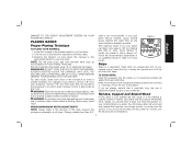
.... 2. The cutter head is in the cutter head clamp are not visible, use a jointer. To properly remove the bow, use a piece of the cup and allows the machine to carefully rotate the cutter head (Fig. 4) until the screws are accessible and the cutter head lock lever (R) engages. Use the T-wrench to remove the four screws in your material is reached. Push the dust shroud to spring back into...
.... 2. The cutter head is in the cutter head clamp are not visible, use a jointer. To properly remove the bow, use a piece of the cup and allows the machine to carefully rotate the cutter head (Fig. 4) until the screws are accessible and the cutter head lock lever (R) engages. Use the T-wrench to remove the four screws in your material is reached. Push the dust shroud to spring back into...
Instruction Manual
Page 10
... the unit. Reset the knife clamp over the pins machined on the top of the T-wrench to lock it into the fan housing and rotate it down to attract the knife clamp and lift it locks into place revealing another knife clamp. 3. Install the screws into the shroud. 3. Follow the same knife change procedure indicated above. 4. Depress the cutter head lock lever (R) as shown...
... the unit. Reset the knife clamp over the pins machined on the top of the T-wrench to lock it into the fan housing and rotate it down to attract the knife clamp and lift it locks into place revealing another knife clamp. 3. Install the screws into the shroud. 3. Follow the same knife change procedure indicated above. 4. Depress the cutter head lock lever (R) as shown...
Instruction Manual
Page 11
... the reset button (X) before you reinstall them. Place the new brushes into the brush holders. 5. If your brushes need replacing, be replaced, begin by a circuit breaker trip, make sure the switch is set from oil, grease, and pitch. English MAINTENANCE WARNING: To reduce the risk of serious personal injury, turn off and disconnect tool from power source before making any adjustments or removing/installing attachments or accessories. Securely re-tighten the screws...
... the reset button (X) before you reinstall them. Place the new brushes into the brush holders. 5. If your brushes need replacing, be replaced, begin by a circuit breaker trip, make sure the switch is set from oil, grease, and pitch. English MAINTENANCE WARNING: To reduce the risk of serious personal injury, turn off and disconnect tool from power source before making any adjustments or removing/installing attachments or accessories. Securely re-tighten the screws...
Instruction Manual
Page 12
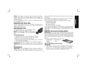
... underside. 2. Check your planer again. Remove the top cover of the base can be used with nails or screws to plane. When servicing this tool could be exposed for use only identical replacement parts. Place planer on your breaker. Replacing the Drive Belt Drive belts are available at DEWALT authorized service centers. Have damaged cords replaced by DEWALT, have not been tested with this product. Change your knives on page 14...
... underside. 2. Check your planer again. Remove the top cover of the base can be used with nails or screws to plane. When servicing this tool could be exposed for use only identical replacement parts. Place planer on your breaker. Replacing the Drive Belt Drive belts are available at DEWALT authorized service centers. Have damaged cords replaced by DEWALT, have not been tested with this product. Change your knives on page 14...
Instruction Manual
Page 13
... the base to use identical replacement parts. TO REMOVE THE TABLES 1. Insert the end of the planer. Three Year Limited Warranty DEWALT will repair, without charge, any defects due to faulty materials or workmanship for planing. English WARNING: The planer could result. Use the T-wrench to push the bolts flush with the base and slide the top hole of the planer, install the bolts and spring...
... the base to use identical replacement parts. TO REMOVE THE TABLES 1. Insert the end of the planer. Three Year Limited Warranty DEWALT will repair, without charge, any defects due to faulty materials or workmanship for planing. English WARNING: The planer could result. Use the T-wrench to push the bolts flush with the base and slide the top hole of the planer, install the bolts and spring...
Instruction Manual
Page 14
... America, see country specific warranty information contained either in Latin America. LATIN AMERICA: This warranty does not apply to the warranty, DEWALT tools are covered by our: 1 YEAR FREE SERVICE DEWALT will maintain the tool and replace worn parts caused by others. For products sold in the packaging, call 1-800-4-DEWALT for a full refund - FREE WARNING LABEL REPLACEMENT: If your DEWALT Power Tool, Laser, or Nailer for any reason, you...
... America, see country specific warranty information contained either in Latin America. LATIN AMERICA: This warranty does not apply to the warranty, DEWALT tools are covered by our: 1 YEAR FREE SERVICE DEWALT will maintain the tool and replace worn parts caused by others. For products sold in the packaging, call 1-800-4-DEWALT for a full refund - FREE WARNING LABEL REPLACEMENT: If your DEWALT Power Tool, Laser, or Nailer for any reason, you...
Instruction Manual
Page 15
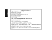
...turn off other electrical loads on another branch circuit by itself. • check for dull knives. Dull knives could cause motor overloading. • drop feed rate to 14ft/min. An overly aggressive cut could cause motor overloading. • reduce depth of cut . English Troubleshooting Guide ...dust shroud. • excess oil/debris from feed rollers. • excessively twisted, cupped or bowed material. • a broken drive belt. IF CHIPS DO NOT EJECT FROM THE REAR OF THE UNIT, CHECK TO SEE: • if the dust shroud is properly in place. • if the circuit breaker needs...
...turn off other electrical loads on another branch circuit by itself. • check for dull knives. Dull knives could cause motor overloading. • drop feed rate to 14ft/min. An overly aggressive cut could cause motor overloading. • reduce depth of cut . English Troubleshooting Guide ...dust shroud. • excess oil/debris from feed rollers. • excessively twisted, cupped or bowed material. • a broken drive belt. IF CHIPS DO NOT EJECT FROM THE REAR OF THE UNIT, CHECK TO SEE: • if the dust shroud is properly in place. • if the circuit breaker needs...

Parts Diagram
Page 2
...5140010-25 5140011-69 Parts List for current parts information. Please visit www.dewaltservicenet.com for DW735X Type 1 Description Qty Required DUST SHROUD 1 PIN 6 LOCK WASHER 4 LEAD 1 SCREW 4 SCREW 3 COVER 1 SHAFT & GEAR 1 RETAINING RING 1 BEARING,BALL 1 BLADE 3 PLANER KNIVES 1 PIN 6 KEY 1 HARDWARE BAG 1 SCREW 24 HARDWARE BAG 1 BLADE HOLDER 3 CUTTER HEAD 1 BALL BEARING 1 BUSHING 1 RETAINING RING 1 PULLEY 1 NUT 1 SHAFT 1 TURRET 1 SPRING 1 COPYRIGHT© 2005. Parts list, pricing, and availability subject to change. All Rights...
...5140010-25 5140011-69 Parts List for current parts information. Please visit www.dewaltservicenet.com for DW735X Type 1 Description Qty Required DUST SHROUD 1 PIN 6 LOCK WASHER 4 LEAD 1 SCREW 4 SCREW 3 COVER 1 SHAFT & GEAR 1 RETAINING RING 1 BEARING,BALL 1 BLADE 3 PLANER KNIVES 1 PIN 6 KEY 1 HARDWARE BAG 1 SCREW 24 HARDWARE BAG 1 BLADE HOLDER 3 CUTTER HEAD 1 BALL BEARING 1 BUSHING 1 RETAINING RING 1 PULLEY 1 NUT 1 SHAFT 1 TURRET 1 SPRING 1 COPYRIGHT© 2005. Parts list, pricing, and availability subject to change. All Rights...

Parts Diagram
Page 3
All Rights Reserved. Parts list, pricing, and availability subject to change. Please visit www.dewaltservicenet.com for DW735X Type 1 Description Qty Required BALL 1 V BELT 1 SCREW 4 HANDLE 2 CHAIN 1 BRACKET 1 WASHER 1 SCREW 7 BOLT 3 SCREW 8 WHEEL ASSEMBLY 1 SCREW 38 INDICATOR 1 PIN 1 SCREW 1 BRACKET 2 SCREW 4 CORD CLAMP 1 CORD & PLUG 1 BRACKET 1 PLATE 1 LEVER 1 SCREW 2 SCREW 4 ID LABEL 1 FRONT COVER 1 SCREW 3 COPYRIGHT© 2005. Page 2 Item Number 26 27 28 29 30 31 32 33 37 45 46 47 48 49 50 51...
All Rights Reserved. Parts list, pricing, and availability subject to change. Please visit www.dewaltservicenet.com for DW735X Type 1 Description Qty Required BALL 1 V BELT 1 SCREW 4 HANDLE 2 CHAIN 1 BRACKET 1 WASHER 1 SCREW 7 BOLT 3 SCREW 8 WHEEL ASSEMBLY 1 SCREW 38 INDICATOR 1 PIN 1 SCREW 1 BRACKET 2 SCREW 4 CORD CLAMP 1 CORD & PLUG 1 BRACKET 1 PLATE 1 LEVER 1 SCREW 2 SCREW 4 ID LABEL 1 FRONT COVER 1 SCREW 3 COPYRIGHT© 2005. Page 2 Item Number 26 27 28 29 30 31 32 33 37 45 46 47 48 49 50 51...

Parts Diagram
Page 4
Parts list, pricing, and availability subject to change. Page 3 All Rights Reserved. Please visit www.dewaltservicenet.com for DW735X Type 1 Description Qty Required SWITCH 1 CIRCUIT BREAKER 1 LOCK WASHER 4 NUT 1 SCREW 2 MICRO SWITCH 1 CAP SCREW 2 WASHER 1 WASHER 2 SCREW 4 PLATE 2 WRENCH 1 WRENCH 1 TOP COVER 1 COVER ASSY. 1 COVER PLATE 2 STRAIN RELIEF 1 COVER 2 SPRING 4 RETAINING RING 2 SPROCKET 4 WASHER 2 RETAINING RING 2 ROD 1 PIN 1 HOLDER 1 CARRIAGE 1 COPYRIGHT© 2005. Item Number 63 64 65 66 67 68 69 70 71 72...
Parts list, pricing, and availability subject to change. Page 3 All Rights Reserved. Please visit www.dewaltservicenet.com for DW735X Type 1 Description Qty Required SWITCH 1 CIRCUIT BREAKER 1 LOCK WASHER 4 NUT 1 SCREW 2 MICRO SWITCH 1 CAP SCREW 2 WASHER 1 WASHER 2 SCREW 4 PLATE 2 WRENCH 1 WRENCH 1 TOP COVER 1 COVER ASSY. 1 COVER PLATE 2 STRAIN RELIEF 1 COVER 2 SPRING 4 RETAINING RING 2 SPROCKET 4 WASHER 2 RETAINING RING 2 ROD 1 PIN 1 HOLDER 1 CARRIAGE 1 COPYRIGHT© 2005. Item Number 63 64 65 66 67 68 69 70 71 72...

Parts Diagram
Page 5
...DW735X Type 1 Description Qty Required PAWL 1 PIN 1 INDICATOR 1 PLATE 1 BUSHING 4 FELT 4 REAR ROLLER 1 BRACKET 4 ROLLER 1 LEAD 1 SCALE PLATE 1 CHAIN 1 SWITCH COVER 1 SWITCH PLATE 1 SHAFT 1 WASHER 2 SPRING 2 IDLER SHAFT 1 SCREW 4 BALL BEARING 1 RETAINING RING 1 COVER 1 CRANK HANDLE 1 BUSHING 4 GEAR 1 CHAIN 1 IDLER SHAFT 1 COPYRIGHT© 2005. Page 4 All Rights Reserved. Item Number...-10 5140011-11 5140011-12 5140011-13 5140011-14 Parts List for current parts information. Parts list, pricing, and availability subject to change.
...DW735X Type 1 Description Qty Required PAWL 1 PIN 1 INDICATOR 1 PLATE 1 BUSHING 4 FELT 4 REAR ROLLER 1 BRACKET 4 ROLLER 1 LEAD 1 SCALE PLATE 1 CHAIN 1 SWITCH COVER 1 SWITCH PLATE 1 SHAFT 1 WASHER 2 SPRING 2 IDLER SHAFT 1 SCREW 4 BALL BEARING 1 RETAINING RING 1 COVER 1 CRANK HANDLE 1 BUSHING 4 GEAR 1 CHAIN 1 IDLER SHAFT 1 COPYRIGHT© 2005. Page 4 All Rights Reserved. Item Number...-10 5140011-11 5140011-12 5140011-13 5140011-14 Parts List for current parts information. Parts list, pricing, and availability subject to change.

Parts Diagram
Page 7
...-58 5140011-64 5140011-65 Parts List for current parts information. Parts list, pricing, and availability subject to change. All Rights Reserved. Page 6 Please visit www.dewaltservicenet.com for DW735X Type 1 Description Qty Required SPRING 1 SPRING 1 SCALE 1 SCREW 2 SET SCREW 1 ADAPTER 1 DUST CHUTE 1 SCREW 4 PLATE 1 LOCK WASHER 2 SCREW 1 SCREW 4 BUSHING 1 CAP 1 INDICATOR 1 SCALE PLATE 1 SCREW 4 PLATE 1 RETAINING RING 2 No Longer Available 2 NAMEPLATE 1 PAD 1 PAD 1 PAD 1 BASE 1 PIN 1 LOCK WASHER 4 COPYRIGHT© 2005.
...-58 5140011-64 5140011-65 Parts List for current parts information. Parts list, pricing, and availability subject to change. All Rights Reserved. Page 6 Please visit www.dewaltservicenet.com for DW735X Type 1 Description Qty Required SPRING 1 SPRING 1 SCALE 1 SCREW 2 SET SCREW 1 ADAPTER 1 DUST CHUTE 1 SCREW 4 PLATE 1 LOCK WASHER 2 SCREW 1 SCREW 4 BUSHING 1 CAP 1 INDICATOR 1 SCALE PLATE 1 SCREW 4 PLATE 1 RETAINING RING 2 No Longer Available 2 NAMEPLATE 1 PAD 1 PAD 1 PAD 1 BASE 1 PIN 1 LOCK WASHER 4 COPYRIGHT© 2005.

Parts Diagram
Page 8
...-92 Parts List for current parts information. Page 7 Please visit www.dewaltservicenet.com for DW735X Type 1 Description Qty Required WASHER 4 FAN HOUSING 1 RETAINING RING 1 SPRING 1 SPRING CLIP 3 SCREW 4 FAN HOUSING 1 NUT 1 WASHER 1 FAN 1 CAP 1 BALL BEARING 2 SCREW 2 FIELD 1 MOTOR CORD 1 ARMATURE 1 MOTOR HOUSING 1 LOCK WASHER 3 SCREW 4 BRUSH CAP 2 BRUSH 2 BRUSH HOLDER 2 SET SCREW 2 PULLEY 1 STRAIN RELIEF 1 SCREW 1 POST 1 COPYRIGHT© 2005. All Rights Reserved. Parts list, pricing, and availability subject to change.
...-92 Parts List for current parts information. Page 7 Please visit www.dewaltservicenet.com for DW735X Type 1 Description Qty Required WASHER 4 FAN HOUSING 1 RETAINING RING 1 SPRING 1 SPRING CLIP 3 SCREW 4 FAN HOUSING 1 NUT 1 WASHER 1 FAN 1 CAP 1 BALL BEARING 2 SCREW 2 FIELD 1 MOTOR CORD 1 ARMATURE 1 MOTOR HOUSING 1 LOCK WASHER 3 SCREW 4 BRUSH CAP 2 BRUSH 2 BRUSH HOLDER 2 SET SCREW 2 PULLEY 1 STRAIN RELIEF 1 SCREW 1 POST 1 COPYRIGHT© 2005. All Rights Reserved. Parts list, pricing, and availability subject to change.


