Instruction Manual
Page 2
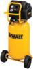
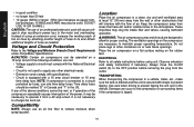
... (56.8 liters) 160 PSI (1103.2 kPa) 200 PSI (1379.0 kPa) 5.4 FIG. 1 2 B C I . Quick Connect F. On/Off Switch B. Pressure Regulator E. Check Valve G. Air Tank Drain Valve I A G D E F H Air Tank Pressure Gauge C. Pressure Switch Pump/Motor Specifications Voltage: Single Phase 120V Minimum branch circuit requirement: 15 A Fuse Type: Time delay Specifications MODEL WEIGHT HEIGHT WIDTH LENGTH AIR TANK CAPACITY (GALLONS) APPROX CUT-IN PRESSURE APPROX. English D55168 Air Compressor A.
... (56.8 liters) 160 PSI (1103.2 kPa) 200 PSI (1379.0 kPa) 5.4 FIG. 1 2 B C I . Quick Connect F. On/Off Switch B. Pressure Regulator E. Check Valve G. Air Tank Drain Valve I A G D E F H Air Tank Pressure Gauge C. Pressure Switch Pump/Motor Specifications Voltage: Single Phase 120V Minimum branch circuit requirement: 15 A Fuse Type: Time delay Specifications MODEL WEIGHT HEIGHT WIDTH LENGTH AIR TANK CAPACITY (GALLONS) APPROX CUT-IN PRESSURE APPROX. English D55168 Air Compressor A.

Instruction Manual
Page 3
...Safety Guidelines The definitions below describe the level of severity for electrical contacts within the motor and pressure switch to spark. • Always operate the compressor in a well ventilated area free of combustible materials, gasoline, or solvent vapors. 3 Wash hands after handling. CAUTION: Indicates a potentially hazardous situation which , if not avoided, may result in minor or moderate injury. When using such tools... type of work with approved safety equipment, always wear OSHA/MSHA/NIOSH approved, properly fitting face mask or respirator when using air tools, basic safety...
...Safety Guidelines The definitions below describe the level of severity for electrical contacts within the motor and pressure switch to spark. • Always operate the compressor in a well ventilated area free of combustible materials, gasoline, or solvent vapors. 3 Wash hands after handling. CAUTION: Indicates a potentially hazardous situation which , if not avoided, may result in minor or moderate injury. When using such tools... type of work with approved safety equipment, always wear OSHA/MSHA/NIOSH approved, properly fitting face mask or respirator when using air tools, basic safety...
Instruction Manual
Page 4
.... • Air obtained directly from the compressor should never be capable of fresh air to the ventilation openings. • Operate compressor in an open area at least 20 feet (6.1 m) away from spray area. Always use certified safety equipment: OSHA/MSHA/NIOSH respiratory protection designed for use with your compressor is operating. • Always turn off and unplug unit when not in use air produced...
.... • Air obtained directly from the compressor should never be capable of fresh air to the ventilation openings. • Operate compressor in an open area at least 20 feet (6.1 m) away from spray area. Always use certified safety equipment: OSHA/MSHA/NIOSH respiratory protection designed for use with your compressor is operating. • Always turn off and unplug unit when not in use air produced...
Instruction Manual
Page 5
... compressor. • Modifications or attempted repairs to the air tank. • Never drill into, weld, or make adjustments or parts substitutions to repair a damaged or leaking air tank. Attachments & accessories: • Exceeding the pressure rating of air tools, spray guns, air operated accessories, tires, and other components which control air tank pressure. • The air tank is not used properly it immediately with a new air tank. • Unauthorized modifications to the safety valve...
... compressor. • Modifications or attempted repairs to the air tank. • Never drill into, weld, or make adjustments or parts substitutions to repair a damaged or leaking air tank. Attachments & accessories: • Exceeding the pressure rating of air tools, spray guns, air operated accessories, tires, and other components which control air tank pressure. • The air tank is not used properly it immediately with a new air tank. • Unauthorized modifications to the safety valve...
Instruction Manual
Page 6
... burns. • Never touch any part of the body or at high speed, resulting in serious injury or death from the air hose and air tank before attempting maintenance, attaching tools or accessories. WARNING: RISK OF HOT SURFACES WHAT CAN HAPPEN HOW TO PREVENT IT • Touching exposed metal such as the compressor head, engine head, engine exhaust or outlet tubes...
... burns. • Never touch any part of the body or at high speed, resulting in serious injury or death from the air hose and air tank before attempting maintenance, attaching tools or accessories. WARNING: RISK OF HOT SURFACES WHAT CAN HAPPEN HOW TO PREVENT IT • Touching exposed metal such as the compressor head, engine head, engine exhaust or outlet tubes...
Instruction Manual
Page 7
.... • Any repairs required on a roof or other elevated position. SAVE THESE INSTRUCTIONS FOR FUTURE USE 7 Never operate compressor on this product may contribute to hearing loss. • Always wear certified safety equipment: ANSI S12.6 (S3.19) hearing protection. Use additional air hose to reach high locations. others. • Become familiar with missing, broken, or unauthorized parts. instructions and warnings in...
.... • Any repairs required on a roof or other elevated position. SAVE THESE INSTRUCTIONS FOR FUTURE USE 7 Never operate compressor on this product may contribute to hearing loss. • Always wear certified safety equipment: ANSI S12.6 (S3.19) hearing protection. Use additional air hose to reach high locations. others. • Become familiar with missing, broken, or unauthorized parts. instructions and warnings in...
Instruction Manual
Page 8
... pressure gauge (C) indicates switch, is expelled. One hand push-to drain condensation at the end of each use . When the amounts. The pressure release valve controlled by popping out at its tank and is used to -connect operation makes connections the factory set cut -in pressure. Pull the knob out and turn clockwise to increase pressure and counterclockwise to lock in the ON position to provide automatic power...
... pressure gauge (C) indicates switch, is expelled. One hand push-to drain condensation at the end of each use . When the amounts. The pressure release valve controlled by popping out at its tank and is used to -connect operation makes connections the factory set cut -in pressure. Pull the knob out and turn clockwise to increase pressure and counterclockwise to lock in the ON position to provide automatic power...
Instruction Manual
Page 9
.... Set the On/Auto/Off lever to whether the compressor is : • a 3-wire extension cord that has a 3-blade grounding plug, and a 3-slot receptacle that will shut off the motor. Plug the power cord into the correct branch circuit receptacle. 4. INSTALLATION Assembly INSTALLING HOSES WARNING: Risk of shock by a qualified electrician. IMPROPER GROUNDING CAN RESULT IN ELECTRICAL SHOCK. The portable air compressor is seated. Extension Cords If an extension cord...
.... Set the On/Auto/Off lever to whether the compressor is : • a 3-wire extension cord that has a 3-blade grounding plug, and a 3-slot receptacle that will shut off the motor. Plug the power cord into the correct branch circuit receptacle. 4. INSTALLATION Assembly INSTALLING HOSES WARNING: Risk of shock by a qualified electrician. IMPROPER GROUNDING CAN RESULT IN ELECTRICAL SHOCK. The portable air compressor is seated. Extension Cords If an extension cord...
Instruction Manual
Page 10
... condition • no longer than 50 feet • 12 gauge (AWG) or larger. (Wire size increases as needed. Always move the On/Off switch (A) to the OFF position before using an extension cord, increase the working reach of the air hose by fuses, use of an undersized extension cord will interfere with the National Electrical Code. • Circuit is connected to a circuit protected by...
... condition • no longer than 50 feet • 12 gauge (AWG) or larger. (Wire size increases as needed. Always move the On/Off switch (A) to the OFF position before using an extension cord, increase the working reach of the air hose by fuses, use of an undersized extension cord will interfere with the National Electrical Code. • Circuit is connected to a circuit protected by...
Instruction Manual
Page 11
... this instruction manual for safety, operation and maintenance instructions. Ensure the On/Off switch (A) is not connected to rest on the rubber bumpers and wheels. NOTE: If hose is in the OFF position. Plug the power cord into the correct branch circuit receptacle. Grasp handle of bursting. Always store compressor in place. 7. Compressed air from the recommended lift points (O). Read the instructions for air tools and accessories. Check...
... this instruction manual for safety, operation and maintenance instructions. Ensure the On/Off switch (A) is not connected to rest on the rubber bumpers and wheels. NOTE: If hose is in the OFF position. Plug the power cord into the correct branch circuit receptacle. Grasp handle of bursting. Always store compressor in place. 7. Compressed air from the recommended lift points (O). Read the instructions for air tools and accessories. Check...

Instruction Manual
Page 12
... before starting service. NOTE: If finished using compressor, follow Steps 2 - 6. Remove hose and accessory. Ensure air tank pressure gauge reads 0 PSI (0 kPa). If not drained, water will start. 5. Move the On/Off switch to the ON position and allow tank pressure to desired setting. Adjust regulator (D) to build. Move On/Off switch (A) to cool down. 6. Drain the air tank, see Draining Air Tank under Features. Open the drain valve (turn lever...
... before starting service. NOTE: If finished using compressor, follow Steps 2 - 6. Remove hose and accessory. Ensure air tank pressure gauge reads 0 PSI (0 kPa). If not drained, water will start. 5. Move the On/Off switch to the ON position and allow tank pressure to desired setting. Adjust regulator (D) to build. Move On/Off switch (A) to cool down. 6. Drain the air tank, see Draining Air Tank under Features. Open the drain valve (turn lever...

Instruction Manual
Page 13
... air tank pressure gauge reads 10 PSI (275.1 kPa), rotate valve to servicing. 1. Checking Air Filter Element (Fig. 1) WARNING: Hot surfaces. Always use Every 100 hours Yearly ● ● ●1 ● 1- NOTE: All compressed air systems generate condensate that the safety valve operates freely. Move compressor into face. Grasp black lever on the safety valve to gradually bleed air from outlet of bursting. Outlet tube, pump head...
... air tank pressure gauge reads 10 PSI (275.1 kPa), rotate valve to servicing. 1. Checking Air Filter Element (Fig. 1) WARNING: Hot surfaces. Always use Every 100 hours Yearly ● ● ●1 ● 1- NOTE: All compressed air systems generate condensate that the safety valve operates freely. Move compressor into face. Grasp black lever on the safety valve to gradually bleed air from outlet of bursting. Outlet tube, pump head...
Instruction Manual
Page 14
... the rating of unsafe operation. FREE WARNING LABEL REPLACEMENT: If your warning labels become illegible or are available for your tool are missing, call 1-800-4-DEWALT. We will repair, without air inlet filter AIR COMPRESSOR PUMP INTAKE AND EXHAUST VALVES Once a year have other qualified service personnel. ACCESSORIES Recommended accessories for use of any other accessory not recommended for all service calls: Model Number Serial Number Date and Place of...
... the rating of unsafe operation. FREE WARNING LABEL REPLACEMENT: If your warning labels become illegible or are available for your tool are missing, call 1-800-4-DEWALT. We will repair, without air inlet filter AIR COMPRESSOR PUMP INTAKE AND EXHAUST VALVES Once a year have other qualified service personnel. ACCESSORIES Recommended accessories for use of any other accessory not recommended for all service calls: Model Number Serial Number Date and Place of...

Instruction Manual
Page 15
... square inch; Cut-In Pressure: While the motor is off, air tank pressure drops when accessory is turned on and begins to build. Cut-Out Pressure: When an air compressor is used. PSI: Pounds per minute. The low pressure at which the motor automatically restarts is called cut -out pressure. The high pressure at which the motor shuts off , protecting your air compressor, it is , the air compressor pump should not run , air pressure in the air...
... square inch; Cut-In Pressure: While the motor is off, air tank pressure drops when accessory is turned on and begins to build. Cut-Out Pressure: When an air compressor is used. PSI: Pounds per minute. The low pressure at which the motor automatically restarts is called cut -out pressure. The high pressure at which the motor shuts off , protecting your air compressor, it is , the air compressor pump should not run , air pressure in the air...
Instruction Manual
Page 16
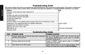
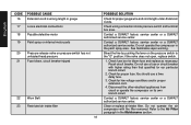
Problem Code Excessive air tank pressure-safety valve pops off 1,2 Air leaks ...3 Air leaks in air tank or at air tank welds 4 Air leaks between head and valve plate 5 Air leaks from safety valve...6 Knocking Noise...6 Pressure reading on the regulated pressure gauge drops when an accessory is used 7 Compressor is not supplying enough air to operate accessories 8,9,10,11,12,23 Regulator knob has continuous air leak 13 Regulator will not shut off air outlet 13 Motor will not run...
Problem Code Excessive air tank pressure-safety valve pops off 1,2 Air leaks ...3 Air leaks in air tank or at air tank welds 4 Air leaks between head and valve plate 5 Air leaks from safety valve...6 Knocking Noise...6 Pressure reading on the regulated pressure gauge drops when an accessory is used 7 Compressor is not supplying enough air to operate accessories 8,9,10,11,12,23 Regulator knob has continuous air leak 13 Regulator will not shut off air outlet 13 Motor will not run...

Instruction Manual
Page 17
... being used 8 Prolonged excessive use of air 9 Compressor is not large enough for some pressure drop to operate accessory. Motor will weaken. Operate safety valve manually by your air compressor, a larger compressor is needed to occur when an accessory is used, adjust the regulator as instructed in pressure of pressure switch. Check the accessory air requirement. CODE POSSIBLE CAUSE 4 Defective air tank 5 Leaking seals 6 Defective safety valve 7 Regulator is not adjusted correctly for accessory being used. WARNING: Risk of air usage. Do not drill...
... being used 8 Prolonged excessive use of air 9 Compressor is not large enough for some pressure drop to operate accessory. Motor will weaken. Operate safety valve manually by your air compressor, a larger compressor is needed to occur when an accessory is used, adjust the regulator as instructed in pressure of pressure switch. Check the accessory air requirement. CODE POSSIBLE CAUSE 4 Defective air tank 5 Leaking seals 6 Defective safety valve 7 Regulator is not adjusted correctly for accessory being used. WARNING: Risk of air usage. Do not drill...
Instruction Manual
Page 18
... pressure switch and terminal box area. English CODE POSSIBLE CAUSE 16 Extension cord is wrong length or gauge 17 Loose electrical connections 18 Possible defective motor 19 Paint spray on internal motor parts 20 Pressure release valve on the pressure switch to the Air Filter paragraph in the paint spray area. Contact a DEWALT factory service center or a DEWALT authorized service center. Disconnect the other electrical appliances from circuit or operate the compressor...
... pressure switch and terminal box area. English CODE POSSIBLE CAUSE 16 Extension cord is wrong length or gauge 17 Loose electrical connections 18 Possible defective motor 19 Paint spray on internal motor parts 20 Pressure release valve on the pressure switch to the Air Filter paragraph in the paint spray area. Contact a DEWALT factory service center or a DEWALT authorized service center. Disconnect the other electrical appliances from circuit or operate the compressor...

Parts Diagram
Page 2
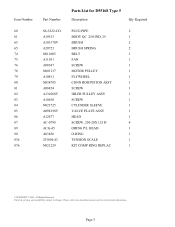
... HEX 1 SUDL-9-1 SCREW #8-32X.375/.34 2 A03857 WASHER 1 N092738 JUMPER 1 ACG-18 CUP SADDLE MOUNT 1 N043321 ROCKER SWITCH 1 CAC-1206-1 CLAMP HOSE .250 ID H 2 D21172 SCREW .250-20X.500 H 4 N015665SV HANDLE ASSEMBLY 1 SSF-3156 SCREW #10-9X.500 THD 1 N074574 CORDSET 1 D28104 SCREW .250-20X.500 P 5 N008792 REGULATOR RPR KIT 1 COPYRIGHT© 2005. Page 1 Parts list, pricing, and availability subject to change. Item Number 1 2 3 4 5 6 7 8 9 10 11...
... HEX 1 SUDL-9-1 SCREW #8-32X.375/.34 2 A03857 WASHER 1 N092738 JUMPER 1 ACG-18 CUP SADDLE MOUNT 1 N043321 ROCKER SWITCH 1 CAC-1206-1 CLAMP HOSE .250 ID H 2 D21172 SCREW .250-20X.500 H 4 N015665SV HANDLE ASSEMBLY 1 SSF-3156 SCREW #10-9X.500 THD 1 N074574 CORDSET 1 D28104 SCREW .250-20X.500 P 5 N008792 REGULATOR RPR KIT 1 COPYRIGHT© 2005. Page 1 Parts list, pricing, and availability subject to change. Item Number 1 2 3 4 5 6 7 8 9 10 11...

Parts Diagram
Page 3
... N094098 Parts List for current parts information. SWITCH 1 SAFETY VALVE 1 BRACKET 1 COVER 1 SHROUD REAR 1 FILTER ASSY. 1 FILTER REPLACEMENT 1 DRAIN VALVE 1 GRILL 1 SCREW 1 HOSE 1 HOSE 1 CLAMP 2 LABEL 1 WARNING LABEL 1 LABEL 1 LABEL 1 LABEL POWER CORD TRI 1 WARNING LABEL 1 LABEL 1 SPEC INFO LABEL 1 COPYRIGHT© 2005. Parts list, pricing, and availability subject to change. Please visit www.dewaltservicenet.com for D55168 Type 5 Description Qty Required REGULATOR BONNET 1 KNOB 1 REGULATOR/MANIFOLD 1 GAUGE 1 FITTING 1 GAUGE 1 MICRO...
... N094098 Parts List for current parts information. SWITCH 1 SAFETY VALVE 1 BRACKET 1 COVER 1 SHROUD REAR 1 FILTER ASSY. 1 FILTER REPLACEMENT 1 DRAIN VALVE 1 GRILL 1 SCREW 1 HOSE 1 HOSE 1 CLAMP 2 LABEL 1 WARNING LABEL 1 LABEL 1 LABEL 1 LABEL POWER CORD TRI 1 WARNING LABEL 1 LABEL 1 SPEC INFO LABEL 1 COPYRIGHT© 2005. Parts list, pricing, and availability subject to change. Please visit www.dewaltservicenet.com for D55168 Type 5 Description Qty Required REGULATOR BONNET 1 KNOB 1 REGULATOR/MANIFOLD 1 GAUGE 1 FITTING 1 GAUGE 1 MICRO...
Parts Diagram
Page 4
... Parts List for current parts information. Please visit www.dewaltservicenet.com for D55168 Type 5 Description Qty Required PLUG PIPE 2 BODY QC .250 IND .25 1 BRUSH 2 BRUSH SPRING 2 BELT 1 FAN 1 SCREW 1 MOTOR PULLEY 1 FLYWHEEL 1 CONN ROD/PISTON ASSY 1 SCREW 1 IDLER PULLEY ASSY 1 SCREW 1 CYLINDER SLEEVE 1 VALVE PLATE ASSY 1 HEAD 1 SCREW .250-20X1.25 H 4 ORING P/L HEAD 1 O-RING 1 TENSION SCALE 1 KIT COMP RING REPLAC 1 COPYRIGHT© 2005. Page 3 Parts list, pricing, and availability subject to change...
... Parts List for current parts information. Please visit www.dewaltservicenet.com for D55168 Type 5 Description Qty Required PLUG PIPE 2 BODY QC .250 IND .25 1 BRUSH 2 BRUSH SPRING 2 BELT 1 FAN 1 SCREW 1 MOTOR PULLEY 1 FLYWHEEL 1 CONN ROD/PISTON ASSY 1 SCREW 1 IDLER PULLEY ASSY 1 SCREW 1 CYLINDER SLEEVE 1 VALVE PLATE ASSY 1 HEAD 1 SCREW .250-20X1.25 H 4 ORING P/L HEAD 1 O-RING 1 TENSION SCALE 1 KIT COMP RING REPLAC 1 COPYRIGHT© 2005. Page 3 Parts list, pricing, and availability subject to change...


