Instruction Manual
Page 2
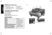
CUT-OUT PRESSURE SCFM @ 100 PSI (689.5 kPa) 135 PSI (930 kPa) .07 FIG. 1 E B DC NOT A STEP A G F H 2 Pressure Regulator E. Air Tank Drain Valve H. Regulated Pressure Gauge D. Safety Valve G. Power Cord Wrap Pump/Motor Specifications Oil free universal motor Bore: 1.57 (40 mm) Stroke: .55 (14 mm) Voltage: Single 120V Minimum branch circuit requirement: 15 A Fuse Type: Time delay Specifications MODEL D55140 WEIGHT HEIGHT 24 lbs...
CUT-OUT PRESSURE SCFM @ 100 PSI (689.5 kPa) 135 PSI (930 kPa) .07 FIG. 1 E B DC NOT A STEP A G F H 2 Pressure Regulator E. Air Tank Drain Valve H. Regulated Pressure Gauge D. Safety Valve G. Power Cord Wrap Pump/Motor Specifications Oil free universal motor Bore: 1.57 (40 mm) Stroke: .55 (14 mm) Voltage: Single 120V Minimum branch circuit requirement: 15 A Fuse Type: Time delay Specifications MODEL D55140 WEIGHT HEIGHT 24 lbs...
Instruction Manual
Page 3
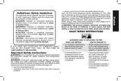
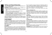
... OR ANY DEWALT TOOL, CALL US TOLL FREE AT: 1-800-4-DEWALT (1-800-433-9258) • It is normal for electrical contacts within the motor and pressure switch to these chemicals are: • lead from lead-based paints • crystalline silica from bricks and cement and other masonry products 3 • If electrical sparks from compressor come into contact with approved safety equipment, always...
... OR ANY DEWALT TOOL, CALL US TOLL FREE AT: 1-800-4-DEWALT (1-800-433-9258) • It is normal for electrical contacts within the motor and pressure switch to these chemicals are: • lead from lead-based paints • crystalline silica from bricks and cement and other masonry products 3 • If electrical sparks from compressor come into contact with approved safety equipment, always...
Instruction Manual
Page 4
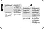
... cause serious injury or death. • Air obtained directly from your specific application. 4 In order to use . DANGER: RISK TO BREATHING (ASPHYXIATION) WHAT CAN HAPPEN HOW TO PREVENT IT • The compressed air directly from the compressor should never be used in conjunction with the compressor must be properly installed. Inline filters and safety equipment used to human consumption. • Sprayed materials...
... cause serious injury or death. • Air obtained directly from your specific application. 4 In order to use . DANGER: RISK TO BREATHING (ASPHYXIATION) WHAT CAN HAPPEN HOW TO PREVENT IT • The compressed air directly from the compressor should never be used in conjunction with the compressor must be properly installed. Inline filters and safety equipment used to human consumption. • Sprayed materials...
Instruction Manual
Page 5
... to withstand specific operating pressures. To find your Air Compressor is not used properly it immediately with a new air tank or replace the entire compressor. • Modifications or attempted repairs to the air tank. • Never drill into, weld, or make adjustments or parts substitutions to repair a damaged or leaking air tank. Replace with national and local electrical codes. 5 All pressure vessels should be UM coded (for assistance. Attachments & accessories: • Exceeding...
... to withstand specific operating pressures. To find your Air Compressor is not used properly it immediately with a new air tank or replace the entire compressor. • Modifications or attempted repairs to the air tank. • Never drill into, weld, or make adjustments or parts substitutions to repair a damaged or leaking air tank. Replace with national and local electrical codes. 5 All pressure vessels should be UM coded (for assistance. Attachments & accessories: • Exceeding...
Instruction Manual
Page 6
... death from the air hose and air tank before attempting maintenance, attaching tools or accessories. See Grounding Instructions under Installation. • Make certain that the electrical circuit to exposed skin and can cause soft tissue damage to which are damaged or removed. • Keep your clothing. • Never operate the compressor with guards or covers which the compressor is connected provides proper electrical grounding, correct...
... death from the air hose and air tank before attempting maintenance, attaching tools or accessories. See Grounding Instructions under Installation. • Make certain that the electrical circuit to exposed skin and can cause soft tissue damage to which are damaged or removed. • Keep your clothing. • Never operate the compressor with guards or covers which the compressor is connected provides proper electrical grounding, correct...
Instruction Manual
Page 7
... death to the operator. • Always operate compressor in ous injury or death to you to moving parts and can expose you or this manual. CAUTION: RISK FROM NOISE WHAT CAN HAPPEN HOW TO PREVENT IT • Under some conditions and duration of alcohol or drugs. Use additional air hose to seri- SAVE THESE INSTRUCTIONS FOR FUTURE USE 7 WARNING: RISK...
... death to the operator. • Always operate compressor in ous injury or death to you to moving parts and can expose you or this manual. CAUTION: RISK FROM NOISE WHAT CAN HAPPEN HOW TO PREVENT IT • Under some conditions and duration of alcohol or drugs. Use additional air hose to seri- SAVE THESE INSTRUCTIONS FOR FUTURE USE 7 WARNING: RISK...

Instruction Manual
Page 8
... the air tank. SAFETY VALVE If the pressure switch does not shut off the air compressor at the end of Quick Connect plugs: Industrial, automotive, and ARO. CHECK VALVE When the air compressor is operating, the check valve is expelled. When the air compressor reaches cut -out G setting). English FEATURES ON (I) /OFF SWITCH (O) Place this fan to blow air through the vent holes in large amounts. It stops the motor...
... the air tank. SAFETY VALVE If the pressure switch does not shut off the air compressor at the end of Quick Connect plugs: Industrial, automotive, and ARO. CHECK VALVE When the air compressor is operating, the check valve is expelled. When the air compressor reaches cut -out G setting). English FEATURES ON (I) /OFF SWITCH (O) Place this fan to blow air through the vent holes in large amounts. It stops the motor...
Instruction Manual
Page 9
... unsafe operation. cian. • Repairs to the cord set and plug (J) with all local codes and ordinances. 2. Grasp the hose and pull to release Quick Connect plug on Quick Connect body back to ensure coupler is properly grounded, have the installation checked by a qualified electri- The portable air compressor is equipped with a cord having a grounding wire with an appropriate grounding plug. 1.The cord set or...
... unsafe operation. cian. • Repairs to the cord set and plug (J) with all local codes and ordinances. 2. Grasp the hose and pull to release Quick Connect plug on Quick Connect body back to ensure coupler is properly grounded, have the installation checked by a qualified electri- The portable air compressor is equipped with a cord having a grounding wire with an appropriate grounding plug. 1.The cord set or...
Instruction Manual
Page 10
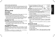
.... Keep the compressor away from the wall or other containers on the rubber feet. CAUTION: Certain air compressors can occur to change the cord set. Contact a DEWALT service center or call 1-800-4-DEWALT for information regarding acceptable noise levels in a clean, dry and well ventilated area at WARNING: Risk of the power, it from the outlet. Observe extension cord safety instructions if necessary.
.... Keep the compressor away from the wall or other containers on the rubber feet. CAUTION: Certain air compressors can occur to change the cord set. Contact a DEWALT service center or call 1-800-4-DEWALT for information regarding acceptable noise levels in a clean, dry and well ventilated area at WARNING: Risk of the power, it from the outlet. Observe extension cord safety instructions if necessary.
Instruction Manual
Page 11
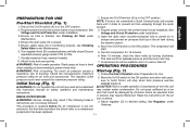
... for safety, operation and maintenance instructions. Attach hose and accessories. WARNING: Risk of unsafe operation. Firmly grasp air hose in hand when installing or disconnecting to build. The compressor will fill to cut -out pressure. Compressed air will stop. 7. Follow Pre-Start Checklist under Installation. 3. The regulator outlet 2. Motor will stop when tank pressure reaches Initial Set-up (Fig. 1) cut -out pressure and the motor will be damaged by turning clockwise. WARNING: Do not operate this instruction manual for Use...
... for safety, operation and maintenance instructions. Attach hose and accessories. WARNING: Risk of unsafe operation. Firmly grasp air hose in hand when installing or disconnecting to build. The compressor will fill to cut -out pressure. Compressed air will stop. 7. Follow Pre-Start Checklist under Installation. 3. The regulator outlet 2. Motor will stop when tank pressure reaches Initial Set-up (Fig. 1) cut -out pressure and the motor will be damaged by turning clockwise. WARNING: Do not operate this instruction manual for Use...
Instruction Manual
Page 12
... drain. WARNING: Risk of bursting. Allow the compressor to prevent hose whip. 4. Maintenance Chart Procedure Before Each Use Daily or after each use Check safety valve X Drain air tank X Checking Safety Valve WARNING: Risk of bursting. Ensure On/Off switch (A) is loud when draining. Ensure air tank pressure gauge reads 0 PSI (0 kPa). Wipe air compressor clean and store in hand when installing or disconnecting to cool down (Fig...
... drain. WARNING: Risk of bursting. Allow the compressor to prevent hose whip. 4. Maintenance Chart Procedure Before Each Use Daily or after each use Check safety valve X Drain air tank X Checking Safety Valve WARNING: Risk of bursting. Ensure On/Off switch (A) is loud when draining. Ensure air tank pressure gauge reads 0 PSI (0 kPa). Wipe air compressor clean and store in hand when installing or disconnecting to cool down (Fig...
Instruction Manual
Page 13
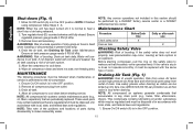
... for all service calls: Model Number Serial Number Date and Place of Purchase Repairs To assure product SAFETY and RELIABILITY, repairs, maintenance and adjustment should be hazardous. Use only accessories rated equal to accessories or damage caused where repairs have been made or attempted by a DEWALT factory service center, a DEWALT authorized service center or other rights which can cause stains. 6. Full One Year Warranty DEWALT heavy duty industrial tools are missing...
... for all service calls: Model Number Serial Number Date and Place of Purchase Repairs To assure product SAFETY and RELIABILITY, repairs, maintenance and adjustment should be hazardous. Use only accessories rated equal to accessories or damage caused where repairs have been made or attempted by a DEWALT factory service center, a DEWALT authorized service center or other rights which can cause stains. 6. Full One Year Warranty DEWALT heavy duty industrial tools are missing...

Instruction Manual
Page 14
... air compressor is turned on and begins to outlet. Branch Circuit: The circuit carrying electricity from pressure higher than 3045 minutes in pressure. Cut-In Pressure: While the motor is off, air tank pressure drops when accessory is capable of your air tank from electrical panel to run more of the following marks: UL, CUL, ETL, CETL, have been evaluated by OSHA certified independent safety...
... air compressor is turned on and begins to outlet. Branch Circuit: The circuit carrying electricity from pressure higher than 3045 minutes in pressure. Cut-In Pressure: While the motor is off, air tank pressure drops when accessory is capable of your air tank from electrical panel to run more of the following marks: UL, CUL, ETL, CETL, have been evaluated by OSHA certified independent safety...
Instruction Manual
Page 15
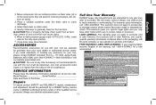
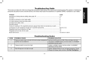
... air tank welds 4 Air leaks between head and valve plate 5 Air leaks from safety valve...6 Knocking Noise...6 Pressure reading on the regulated pressure gauge drops when an accessory is used 7 Compressor is not supplying enough air to operate accessories 8,9,10,11,12 Regulator knob has continuous air leak 13 Regulator will not shut off air outlet 13 Motor will not run ...14,15,16,17,18,19 CODE 1 2 3 Troubleshooting Codes POSSIBLE CAUSE POSSIBLE SOLUTION Pressure switch...
... air tank welds 4 Air leaks between head and valve plate 5 Air leaks from safety valve...6 Knocking Noise...6 Pressure reading on the regulated pressure gauge drops when an accessory is used 7 Compressor is not supplying enough air to operate accessories 8,9,10,11,12 Regulator knob has continuous air leak 13 Regulator will not shut off air outlet 13 Motor will not run ...14,15,16,17,18,19 CODE 1 2 3 Troubleshooting Codes POSSIBLE CAUSE POSSIBLE SOLUTION Pressure switch...
Instruction Manual
Page 16
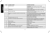
... is normal for proper gauge wire and cord length. Tighten fittings. Remove, clean or replace. Do not drill into, weld or otherwise modify air tank or it will weaken. Operate safety valve manually by your air compressor, a larger compressor is needed to occur when an accessory is used, adjust the regulator as instructed in air hose 11 Check valve restricted 12 Air leaks 13 Regulator is damaged 14 Motor overload protection switch has tripped 15 Extension...
... is normal for proper gauge wire and cord length. Tighten fittings. Remove, clean or replace. Do not drill into, weld or otherwise modify air tank or it will weaken. Operate safety valve manually by your air compressor, a larger compressor is needed to occur when an accessory is used, adjust the regulator as instructed in air hose 11 Check valve restricted 12 Air leaks 13 Regulator is damaged 14 Motor overload protection switch has tripped 15 Extension...
Instruction Manual
Page 17
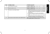
.... Motor will start automatically when tank pressure drops below cut -in pressure of pressure switch. 17 English CODE POSSIBLE CAUSE 16 Loose electrical connections 17 Possible defective motor. 18 Fuse blown, circuit breaker tripped 19 Tank pressure exceeds pressure switch cut -in pressure POSSIBLE SOLUTION Contact a DEWALT factory service center or a DEWALT authorized service center. Contact a DEWALT factory service center or a DEWALT authorized service center. 1. Disconnect the other electrical appliances from circuit or operate the compressor...
.... Motor will start automatically when tank pressure drops below cut -in pressure of pressure switch. 17 English CODE POSSIBLE CAUSE 16 Loose electrical connections 17 Possible defective motor. 18 Fuse blown, circuit breaker tripped 19 Tank pressure exceeds pressure switch cut -in pressure POSSIBLE SOLUTION Contact a DEWALT factory service center or a DEWALT authorized service center. Contact a DEWALT factory service center or a DEWALT authorized service center. 1. Disconnect the other electrical appliances from circuit or operate the compressor...
Instruction Manual
Page 55
DEWALT Industrial Tool Co., 701 Joppa Road, Baltimore, MD 21286 (AUG06) Form No. the "D" shaped air intake grill; the kit box configuration; A18021 r1 D55140 Copyright © 2006 DEWALT The following are trademarks for one or more DEWALT power tools: the yellow and black color scheme; and the array of lozenge-shaped humps on the surface of pyramids on the handgrip; the array of the tool.
DEWALT Industrial Tool Co., 701 Joppa Road, Baltimore, MD 21286 (AUG06) Form No. the "D" shaped air intake grill; the kit box configuration; A18021 r1 D55140 Copyright © 2006 DEWALT The following are trademarks for one or more DEWALT power tools: the yellow and black color scheme; and the array of lozenge-shaped humps on the surface of pyramids on the handgrip; the array of the tool.
Parts Diagram
Page 2
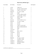
... 5140040-28 5140040-29 5140040-30 Parts List for current parts information. Please visit www.dewaltservicenet.com for D55140 Type 1 Description Qty Required TUBE PLUG 2 KIT ISOLATOR W/SCREW 4 SCREW .250-20X.750 H 4 No Longer Available 4 PUMP 1 FITTING 90DEG ELBOW 1 CLAMP HOSE .250 ID H 2 HOSE CLAMP 2 ELBOW 1 VALVE SAFETY 150 .25 1 No Longer Available 1 GAUGE 2 GAUGE 2 SCREW .250-20X.500 P 6 REGULATOR/MANIFOLD 1 HOSE 1 NUT 4 BALL VALVE 1 DECAL 1 DECAL 1 DECAL 1 LABEL 1 No...
... 5140040-28 5140040-29 5140040-30 Parts List for current parts information. Please visit www.dewaltservicenet.com for D55140 Type 1 Description Qty Required TUBE PLUG 2 KIT ISOLATOR W/SCREW 4 SCREW .250-20X.750 H 4 No Longer Available 4 PUMP 1 FITTING 90DEG ELBOW 1 CLAMP HOSE .250 ID H 2 HOSE CLAMP 2 ELBOW 1 VALVE SAFETY 150 .25 1 No Longer Available 1 GAUGE 2 GAUGE 2 SCREW .250-20X.500 P 6 REGULATOR/MANIFOLD 1 HOSE 1 NUT 4 BALL VALVE 1 DECAL 1 DECAL 1 DECAL 1 LABEL 1 No...
Parts Diagram
Page 3
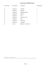
All Rights Reserved. Parts list, pricing, and availability subject to change. Item Number 29 30 31 32 33 34 35 36 37 38 Part Number 5140040-31 5140040-32 5140040-33 5140040-34 5140040-35 5140040-36 5140040-37 5140040-38 5140040-39 A19513 Parts List for current parts information. Page 2 Please visit www.dewaltservicenet.com for D55140 Type 1 Description Qty Required SCREWS 2 SCREWS 6 SHROUD RIGHT 1 SWITCH 1 FAN 1 CHECK VALVE 1 FUSE 1 PCB ASSY 1 CORDSET 1 BODY QC .250 IND .25 1 COPYRIGHT© 2005.
All Rights Reserved. Parts list, pricing, and availability subject to change. Item Number 29 30 31 32 33 34 35 36 37 38 Part Number 5140040-31 5140040-32 5140040-33 5140040-34 5140040-35 5140040-36 5140040-37 5140040-38 5140040-39 A19513 Parts List for current parts information. Page 2 Please visit www.dewaltservicenet.com for D55140 Type 1 Description Qty Required SCREWS 2 SCREWS 6 SHROUD RIGHT 1 SWITCH 1 FAN 1 CHECK VALVE 1 FUSE 1 PCB ASSY 1 CORDSET 1 BODY QC .250 IND .25 1 COPYRIGHT© 2005.


