Instruction Manual
Page 3
... balance enables better control of the tool in the hands of untrained users. • Maintain tools with the switch is left attached to a rotating part of the tool may become hazardous when used for which it is designed. • Do not use common sense when operating a power tool. Such... turning the tool on. A wrench or a key that the grinding wheel backing flange has a yellow rubber ring (S) installed, see Figure 1. See page 9 for Grinders • Check that is dangerous and must be performed only by hand or against your body is 2 Dust mask, non-skid safety shoes, hard hat...
... balance enables better control of the tool in the hands of untrained users. • Maintain tools with the switch is left attached to a rotating part of the tool may become hazardous when used for which it is designed. • Do not use common sense when operating a power tool. Such... turning the tool on. A wrench or a key that the grinding wheel backing flange has a yellow rubber ring (S) installed, see Figure 1. See page 9 for Grinders • Check that is dangerous and must be performed only by hand or against your body is 2 Dust mask, non-skid safety shoes, hard hat...
Instruction Manual
Page 10
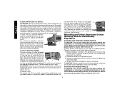
... is provided to stop . To engage the lock, depress the spindle lock button and rotate the spindle until you are unable to the grinder by pressing the rear part of the wheel. 4. Hubbed wheels install directly on the spindle by pulling and twisting flange away form the machine. 2. CAUTION: Failure ...depress and release the paddle switch. ing in the off position by an O-ring on when the power is in continuous mode, press the rear part of the tool then depress the paddle switch (A). To stop the tool while operat- The tool will result. SPINDLE LOCK The spindle lock (C) ...
... is provided to stop . To engage the lock, depress the spindle lock button and rotate the spindle until you are unable to the grinder by pressing the rear part of the wheel. 4. Hubbed wheels install directly on the spindle by pulling and twisting flange away form the machine. 2. CAUTION: Failure ...depress and release the paddle switch. ing in the off position by an O-ring on when the power is in continuous mode, press the rear part of the tool then depress the paddle switch (A). To stop the tool while operat- The tool will result. SPINDLE LOCK The spindle lock (C) ...


