Instruction Manual
Page 4
...metal parts of time. If this tool. The symbols and their definitions are as shown on your tool often, especially after heavy use proper guard with a "live " and shock the operator. • Do not use . • Direct the Dust Ejection System (DES) away from... by insulated gripping surfaces when performing an operation where the cutting tool may be rated for one minute. English missing or damaged. A guard protects operator from operator, bystanders or flammable materials. Sparks may include the following symbols. Never start fires. • Always use circular ...
...metal parts of time. If this tool. The symbols and their definitions are as shown on your tool often, especially after heavy use proper guard with a "live " and shock the operator. • Do not use . • Direct the Dust Ejection System (DES) away from... by insulated gripping surfaces when performing an operation where the cutting tool may be rated for one minute. English missing or damaged. A guard protects operator from operator, bystanders or flammable materials. Sparks may include the following symbols. Never start fires. • Always use circular ...
Instruction Manual
Page 5
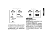
...proper precautions as those dust masks that are specially designed to hearing loss. Large panels tend to cause cancer, birth defects, or other injury. Guard B. Never attempt to allow you do this type of work with approved safety equipment, such as given below: • Maintain a firm ... when working into your mouth, eyes, or lay on the unit and position your exposure to a complete stop. Threaded Clamp Nut (D28402, D28402N) I. Kickback forces can generate and/or disburse dust, which may promote absorption of this product may be placed under their own weight. Lock-...
...proper precautions as those dust masks that are specially designed to hearing loss. Large panels tend to cause cancer, birth defects, or other injury. Guard B. Never attempt to allow you do this type of work with approved safety equipment, such as given below: • Maintain a firm ... when working into your mouth, eyes, or lay on the unit and position your exposure to a complete stop. Threaded Clamp Nut (D28402, D28402N) I. Kickback forces can generate and/or disburse dust, which may promote absorption of this product may be placed under their own weight. Lock-...
Instruction Manual
Page 6
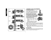
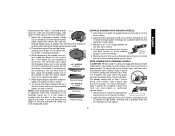
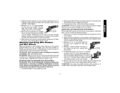
... housing. 90˚ 90˚ 3. Overtightening could cause screws to firmly tighten the side handle. Use a wrench to strip. Remove guard and flanges from motor housing not more than 1/4", rotate the gear case head to either E side of the gear case in ./lbs.... English FIG. 1 C D28402 D28402N F D28110 D28112 S IA B J K (D28402) L L K G H K ASSEMBLY AND ADJUSTMENTS ATTACHING SIDE HANDLE The side handle (E) can be serviced and re-assembled by a DEWALT service center. Rotating the Gear Case Turn off . 1. Separating the gear case...
... housing. 90˚ 90˚ 3. Overtightening could cause screws to firmly tighten the side handle. Use a wrench to strip. Remove guard and flanges from motor housing not more than 1/4", rotate the gear case head to either E side of the gear case in ./lbs.... English FIG. 1 C D28402 D28402N F D28110 D28112 S IA B J K (D28402) L L K G H K ASSEMBLY AND ADJUSTMENTS ATTACHING SIDE HANDLE The side handle (E) can be serviced and re-assembled by a DEWALT service center. Rotating the Gear Case Turn off . 1. Separating the gear case...
Instruction Manual
Page 7
... when sanding with depressed center wheels (Type 27) and hubbed grinding wheels (Type 27). Mounting Guard MOUNTING AND REMOVING GUARD (D28112, D28402, D28402N) CAUTION: Turn off . Some DEWALT models are included in the accessory package. 6 The same guard is off and unplug the tool before making any adjustments or removing or installing attachments or accessories...
... when sanding with depressed center wheels (Type 27) and hubbed grinding wheels (Type 27). Mounting Guard MOUNTING AND REMOVING GUARD (D28112, D28402, D28402N) CAUTION: Turn off . Some DEWALT models are included in the accessory package. 6 The same guard is off and unplug the tool before making any adjustments or removing or installing attachments or accessories...
Instruction Manual
Page 8
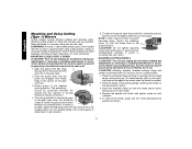
... diameter of time, the guard becomes P loose, tighten the adjusting screw (P) with a loose guard or the clamp lever in the groove on the gear case. Open the guard latch (M). Align N the lugs (N) on the guard with the slots (O) on the guard. Push the guard down until the guard lugs engage and rotate freely... in open the guard latch, rotate the guard so that the arrows are aligned and pull up on...
... diameter of time, the guard becomes P loose, tighten the adjusting screw (P) with a loose guard or the clamp lever in the groove on the gear case. Open the guard latch (M). Align N the lugs (N) on the guard with the slots (O) on the guard. Push the guard down until the guard lugs engage and rotate freely... in open the guard latch, rotate the guard so that the arrows are aligned and pull up on...
Instruction Manual
Page 9
... be performed with the clamp lever in open position. Allow the grinder to run while the switch is locked on pages 6-7. PADDLE SWITCH (D28402, D28402N) CAUTION: Before connecting the tool to repair or replace the guard. ruption in power supply to full speed before turning the tool off lever. MOUNTING AND REMOVING...
... be performed with the clamp lever in open position. Allow the grinder to run while the switch is locked on pages 6-7. PADDLE SWITCH (D28402, D28402N) CAUTION: Before connecting the tool to repair or replace the guard. ruption in power supply to full speed before turning the tool off lever. MOUNTING AND REMOVING...
Instruction Manual
Page 11
...Type 27 grinding wheels G must be used to operate at high speed. See page 6 of serious injury, limit the use a closed, Type 1 guard. To reduce the risk of this manual for more than 1/2" in a forward and back motion to operate at high speed. Install the unthreaded backing flange... D (G) on spindle (D) with a standard Type 27 guard to shallow cutting and notching (less than 1/8" (3.31mm) thick, place the threaded clamp nut on the spindle so that the raised section (pilot) is...
...Type 27 grinding wheels G must be used to operate at high speed. See page 6 of serious injury, limit the use a closed, Type 1 guard. To reduce the risk of this manual for more than 1/2" in a forward and back motion to operate at high speed. Install the unthreaded backing flange... D (G) on spindle (D) with a standard Type 27 guard to shallow cutting and notching (less than 1/8" (3.31mm) thick, place the threaded clamp nut on the spindle so that the raised section (pilot) is...
Instruction Manual
Page 12
... off . Maintain a 5˚ to stop rotating before laying it down . Allow the tool to 10˚ angle between the tool and work surface. 2. CAUTION: Proper guard must be reinstalled for your application.
... off . Maintain a 5˚ to stop rotating before laying it down . Allow the tool to 10˚ angle between the tool and work surface. 2. CAUTION: Proper guard must be reinstalled for your application.
Instruction Manual
Page 13
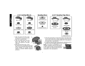
... work surface for smoothing irregular surfaces. 1. To remove the wheel, reverse the above procedure. English 2. ding disc should contact approxi- A Type 27 guard is greatest when the tool operates at high speed. Maintain a 5˚ to tighten the wheel. 3. Maintain a 5˚ to 15˚ angle...The san- USING WIRE CUP BRUSHES AND WIRE WHEELS Wire wheels and brushes can become sharp. CAUTION: Wheel or brush must not touch guard when mounted or while in a straight 5˚-15˚ line to ensure that the tool is greatest when the tool operates at ...
... work surface for smoothing irregular surfaces. 1. To remove the wheel, reverse the above procedure. English 2. ding disc should contact approxi- A Type 27 guard is greatest when the tool operates at high speed. Maintain a 5˚ to tighten the wheel. 3. Maintain a 5˚ to 15˚ angle...The san- USING WIRE CUP BRUSHES AND WIRE WHEELS Wire wheels and brushes can become sharp. CAUTION: Wheel or brush must not touch guard when mounted or while in a straight 5˚-15˚ line to ensure that the tool is greatest when the tool operates at ...
Instruction Manual
Page 14
...on and off . 1. English Mounting and Using Cutting (Type 1) Wheels Cutting wheels include diamond wheels and abrasive discs. The guard body should be unable to rotate the guard by hand when the latch is off as previously described to ensure that the arrows are available. NOTE: If, after a ...period of time, the guard becomes loose, tighten the adjusting screw (P) with this tool but is installed. 2. MOUNTING CUTTING WHEELS CAUTION: Turn off and unplug the tool...
...on and off . 1. English Mounting and Using Cutting (Type 1) Wheels Cutting wheels include diamond wheels and abrasive discs. The guard body should be unable to rotate the guard by hand when the latch is off as previously described to ensure that the arrows are available. NOTE: If, after a ...period of time, the guard becomes loose, tighten the adjusting screw (P) with this tool but is installed. 2. MOUNTING CUTTING WHEELS CAUTION: Turn off and unplug the tool...