
Literature/Product Sheet
Page 1
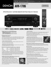
...each source input and surround mode, in turn ensures that all channels respond with discrete power output devices on all of DENON's high-grade A/V receivers, the AVR-1705 lets you adjust delay times and other parameters so that supports the large transformer has been designed to 100 kHz. s ... the AVR-1705 have been placed in the home theater without correction, the high-frequency range is too strong. s DENON's Basic Design for High-Quality Sound Reproduction • Power Transformer for High Power Driven The chassis that you need to do not need to a theater's front speakers being ...
...each source input and surround mode, in turn ensures that all channels respond with discrete power output devices on all of DENON's high-grade A/V receivers, the AVR-1705 lets you adjust delay times and other parameters so that supports the large transformer has been designed to 100 kHz. s ... the AVR-1705 have been placed in the home theater without correction, the high-frequency range is too strong. s DENON's Basic Design for High-Quality Sound Reproduction • Power Transformer for High Power Driven The chassis that you need to do not need to a theater's front speakers being ...

Literature/Product Sheet
Page 2
... in your home theater system, including codes for selected DENON models, along with remote control codes from all six speakers. Jazz Club 5. Video Game 6. Matrix 7. Mono Movie s Adjustable Cross-Over Switching The AVR-1705 supports subwoofer cross-over frequencies: 40/60/80/100/...-D device are power amp stage values. This 6 Channel Stereo mode was originally developed by DENON to enhance music lovers' enjoyment of DTS Technology. NEW MODEL I N F O R M AT I O N AVR-1705 s Multi-Function Preset Memory Remote Controller with Glo-keys The supplied system remote controller features ...
... in your home theater system, including codes for selected DENON models, along with remote control codes from all six speakers. Jazz Club 5. Video Game 6. Matrix 7. Mono Movie s Adjustable Cross-Over Switching The AVR-1705 supports subwoofer cross-over frequencies: 40/60/80/100/...-D device are power amp stage values. This 6 Channel Stereo mode was originally developed by DENON to enhance music lovers' enjoyment of DTS Technology. NEW MODEL I N F O R M AT I O N AVR-1705 s Multi-Function Preset Memory Remote Controller with Glo-keys The supplied system remote controller features ...
Owners Manual
Page 4
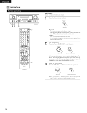
... the Remote Control Unit 17 ⁄0 Setting up the Speaker Systems 9 , Connections 10 ~ 16 . Always set ... a V. ENGLISH 2 INTRODUCTION Thank you review the contents of this manual before proceeding. AUX terminal The AVR-1705/685's front panel is provided with an immense array of Preset Codes 128 ~ 132 2 ACCESSORIES Check that...on Installation 5 c Cautions on Check once again that all other audio components when moving the set for choosing the DENON A/V Surround receiver. As this instructions may differ from the actual set . • Before turning the power operation switch...
... the Remote Control Unit 17 ⁄0 Setting up the Speaker Systems 9 , Connections 10 ~ 16 . Always set ... a V. ENGLISH 2 INTRODUCTION Thank you review the contents of this manual before proceeding. AUX terminal The AVR-1705/685's front panel is provided with an immense array of Preset Codes 128 ~ 132 2 ACCESSORIES Check that...on Installation 5 c Cautions on Check once again that all other audio components when moving the set for choosing the DENON A/V Surround receiver. As this instructions may differ from the actual set . • Before turning the power operation switch...
Owners Manual
Page 5
... input function is switched when nothing is connected to the input jacks. • Muting of PRE OUT jack, HEADPHONE jack and SPEAKER terminals The PRE OUT jack, HEADPHONE jack and SPEAKER terminals include a muting circuit. Always wait until the muting circuit turns off ) when you leave home for several seconds after the...
... input function is switched when nothing is connected to the input jacks. • Muting of PRE OUT jack, HEADPHONE jack and SPEAKER terminals The PRE OUT jack, HEADPHONE jack and SPEAKER terminals include a muting circuit. Always wait until the muting circuit turns off ) when you leave home for several seconds after the...
Owners Manual
Page 7
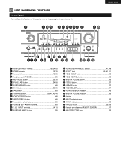
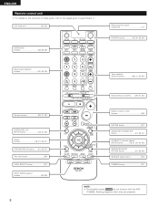
... @1 @0 r u o !1 !3 q w e ty i !0 !2 !4 !5 !6 !7 !8 !9 q Power ON/STANDBY switch 19, 34, 53) w POWER indicator 19, 34) e Power switch 19, 34) r Headphone jack (PHONES 37) t INPUT MODE button 35, 38) y SPEAKER A/B buttons 34, 56) u SURROUNDBACK button 45) i EXT. IN button 35, 38) o BAND button 54) !0 STANDARD button 39, 41, 43, 45) !1 5CH/6CH STEREO button 49...
... @1 @0 r u o !1 !3 q w e ty i !0 !2 !4 !5 !6 !7 !8 !9 q Power ON/STANDBY switch 19, 34, 53) w POWER indicator 19, 34) e Power switch 19, 34) r Headphone jack (PHONES 37) t INPUT MODE button 35, 38) y SPEAKER A/B buttons 34, 56) u SURROUNDBACK button 45) i EXT. IN button 35, 38) o BAND button 54) !0 STANDARD button 39, 41, 43, 45) !1 5CH/6CH STEREO button 49...
Owners Manual
Page 8
... 37) SURROUND PARAMETER button 31, 32, 41) CH SELECT (channel select)/ ENTER button 18, 31, 32, 40, 42) SURROUND BACK/ RETURN button 31, 32, 45) SPEAKER select button 34) DIMMER button 37) NOTE: • The shaded buttons do not function with the AVR- 1705/685. (Nothing happens when they are pressed.)
... 37) SURROUND PARAMETER button 31, 32, 41) CH SELECT (channel select)/ ENTER button 18, 31, 32, 40, 42) SURROUND BACK/ RETURN button 31, 32, 45) SPEAKER select button 34) DIMMER button 37) NOTE: • The shaded buttons do not function with the AVR- 1705/685. (Nothing happens when they are pressed.)

Owners Manual
Page 9
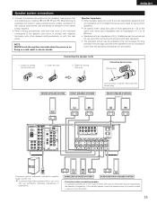
...layout Basic system layout • The following is an example of the basic layout for a system consisting of seven speaker systems and a television monitor: Subwoofer Center speaker system Surround back speaker system Front speaker systems Set these steps. Step 1 (page 9 to 16) Choose the best location to 28) Finally, setting up... the system. Step 3 (page 18 to setup the Speakers and connecting the components. Following these at the sides of the TV or screen with their front surfaces as flush with the front of the ...
...layout Basic system layout • The following is an example of the basic layout for a system consisting of seven speaker systems and a television monitor: Subwoofer Center speaker system Surround back speaker system Front speaker systems Set these steps. Step 1 (page 9 to 16) Choose the best location to 28) Finally, setting up... the system. Step 3 (page 18 to setup the Speakers and connecting the components. Following these at the sides of the TV or screen with their front surfaces as flush with the front of the ...
Owners Manual
Page 15
...Doing so could result in electric shocks. Connecting banana plugs Banana plug CENTER SPEAKER SYSTEM FRONT SPEAKER SYSTEMS System A Turn clockwise to a position where it does not have this effect. 15 FRONT SPEAKER SYSTEMS System B (L) (R) (L) (R) (L) (R) Connection jack for subwoofer ...sure that like polarities are use separately, speakers with an impedance of 6 to 16 Ω/ohms can be disturbed by the speaker's magnetism. SURROUND SPEAKER SYSTEMS SURROUND BACK SPEAKER SYSTEM • Precautions when connecting speakers If a speaker is on the screen may be activated...
...Doing so could result in electric shocks. Connecting banana plugs Banana plug CENTER SPEAKER SYSTEM FRONT SPEAKER SYSTEMS System A Turn clockwise to a position where it does not have this effect. 15 FRONT SPEAKER SYSTEMS System B (L) (R) (L) (R) (L) (R) Connection jack for subwoofer ...sure that like polarities are use separately, speakers with an impedance of 6 to 16 Ω/ohms can be disturbed by the speaker's magnetism. SURROUND SPEAKER SYSTEMS SURROUND BACK SPEAKER SYSTEM • Precautions when connecting speakers If a speaker is on the screen may be activated...
Owners Manual
Page 16
...and the power supply indicator LED flashes. Note on speaker impedance • The protector circuit may be sure to...speaker cables or input cables, and wait for the set 's power, wait for the unit to protect the speakers ...If the protection circuit is played for example speakers with an impedance lower than 4 Ω/ohms) are ... When the protection circuit is activated, the speaker output is used at high volumes when speakers with an impedance of this occur, please ...cut off. If the protector circuit is activated, the speaker output is very hot. Should this circuit is to ...
...and the power supply indicator LED flashes. Note on speaker impedance • The protector circuit may be sure to...speaker cables or input cables, and wait for the set 's power, wait for the unit to protect the speakers ...If the protection circuit is played for example speakers with an impedance lower than 4 Ω/ohms) are ... When the protection circuit is activated, the speaker output is used at high volumes when speakers with an impedance of this occur, please ...cut off. If the protector circuit is activated, the speaker output is very hot. Should this circuit is to ...
Owners Manual
Page 18
...12 ft Center 12 ft Surround L Surround R Surround Back Subwoofer 10 ft 10 ft 10 ft 12 ft Subwoofer Mode This selects the subwoofer speaker for the different input sources. Digital Inputs Input source Front L Front R Center 0 dB 0 dB 0 dB COAXIAL OPTICAL1 CD DVD/VDP ...to automatically set up the listening room's AV system centered around the this to switch the display. These settings are produced from the speakers and subwoofer according to the listening position. Subwoofer mode = Normal Crossover Frequency Set the frequency (Hz) below on the display. Ext...
...12 ft Center 12 ft Surround L Surround R Surround Back Subwoofer 10 ft 10 ft 10 ft 12 ft Subwoofer Mode This selects the subwoofer speaker for the different input sources. Digital Inputs Input source Front L Front R Center 0 dB 0 dB 0 dB COAXIAL OPTICAL1 CD DVD/VDP ...to automatically set up the listening room's AV system centered around the this to switch the display. These settings are produced from the speakers and subwoofer according to the listening position. Subwoofer mode = Normal Crossover Frequency Set the frequency (Hz) below on the display. Ext...

Owners Manual
Page 19
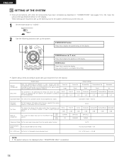
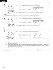
...Power switch (button) . • ¢ ON The power turns on and indicator is off. The changes to the speaker configuration set up can be selected for the front speakers, "Large" cannot be finished at any time. In this position to turn the power on and off from the remote control...button (down ) button to switch to the settings made up . NOTE: Press the SYSTEM SETUP button again to finish system set up to the surround speaker setting. Press the Power ON/STANDBY switch (button). (Main unit) (Remote control unit) 4 Press the SYSTEM SETUP button to enter the setting. *...
...Power switch (button) . • ¢ ON The power turns on and indicator is off. The changes to the speaker configuration set up can be selected for the front speakers, "Large" cannot be finished at any time. In this position to turn the power on and off from the remote control...button (down ) button to switch to the settings made up . NOTE: Press the SYSTEM SETUP button again to finish system set up to the surround speaker setting. Press the Power ON/STANDBY switch (button). (Main unit) (Remote control unit) 4 Press the SYSTEM SETUP button to enter the setting. *...
Owners Manual
Page 20
...or (left) button (right) button (down) button to enter the settings and switch to the Speaker Distance setting. • Parameters Large...... Select this when using speakers that have sufficient performance for reproducing bass sound below the frequency set for the Crossover Frequency mode is...Frequency mode. Select "Yes" when a subwoofer is installed, "No" when a subwoofer is set for the surround speakers. 4 Use the (left) and (right) buttons to select your surround back speaker type. 4 S.BACK SMALL (Initial) LARGE SMALL NONE Press the ENTER or (left) button (right) button ...
...or (left) button (right) button (down) button to enter the settings and switch to the Speaker Distance setting. • Parameters Large...... Select this when using speakers that have sufficient performance for reproducing bass sound below the frequency set for the Crossover Frequency mode is...Frequency mode. Select "Yes" when a subwoofer is installed, "No" when a subwoofer is set for the surround speakers. 4 Use the (left) and (right) buttons to select your surround back speaker type. 4 S.BACK SMALL (Initial) LARGE SMALL NONE Press the ENTER or (left) button (right) button ...

Owners Manual
Page 21
... value closest to the measured distance. Press the ENTER or (down ) button to switch to the front R speaker setting. 2 Use the (left ) and (right) buttons to set the delay time for every speaker should be 15 ft or less. Press the ENTER or (down ) button to switch to the surround... on the diagram at the right). ENGLISH Setting the delay time • Input the distance between the listening position and the different speakers to set the distance from the front R speaker to the listening position. 7 FRONT R 12ft • The number changes in units of 1 foot each time one of the ...
... value closest to the measured distance. Press the ENTER or (down ) button to switch to the front R speaker setting. 2 Use the (left ) and (right) buttons to set the delay time for every speaker should be 15 ft or less. Press the ENTER or (down ) button to switch to the surround... on the diagram at the right). ENGLISH Setting the delay time • Input the distance between the listening position and the different speakers to set the distance from the front R speaker to the listening position. 7 FRONT R 12ft • The number changes in units of 1 foot each time one of the ...

Owners Manual
Page 22
...ENTER or (down ) button to switch to the subwoofer setting. Use the position. (left) and (right) buttons to set the distance from the surround R speakers to the listening 10 SURR.R 10ft • The number changes in units of 1 foot each time one of the buttons is pressed. ENGLISH 4 5 6 7... Use the position. (left) and (right) buttons to set the distance from the surround L speakers to the listening 9 SURR.L 10ft • The number changes in units of 1 foot each time one of the buttons is pressed. Select the value closest...
...ENTER or (down ) button to switch to the subwoofer setting. Use the position. (left) and (right) buttons to set the distance from the surround R speakers to the listening 10 SURR.R 10ft • The number changes in units of 1 foot each time one of the buttons is pressed. ENGLISH 4 5 6 7... Use the position. (left) and (right) buttons to set the distance from the surround L speakers to the listening 9 SURR.L 10ft • The number changes in units of 1 foot each time one of the buttons is pressed. Select the value closest...
Owners Manual
Page 23
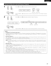
...LARGE" are produced simultaneously from those channels and the subwoofer channel. Crossover Frequency - • When "Subwoofer" is set to "Yes" at the "Speaker Configuration Setting", set the frequency (Hz) below the crossover frequency is cut, and the cut bass sound is set to "SMALL" in the setup... are LFE signals (during playback of Dolby Digital or DTS signals) and the low frequency signal range of the low frequency range in the "Speaker Configuration" settings (see pages 19, 20). ENGLISH Setting the Subwoofer mode and Crossover Frequency 1 Use the (left) and (right) buttons to...
...LARGE" are produced simultaneously from those channels and the subwoofer channel. Crossover Frequency - • When "Subwoofer" is set to "Yes" at the "Speaker Configuration Setting", set the frequency (Hz) below the crossover frequency is cut, and the cut bass sound is set to "SMALL" in the setup... are LFE signals (during playback of Dolby Digital or DTS signals) and the low frequency signal range of the low frequency range in the "Speaker Configuration" settings (see pages 19, 20). ENGLISH Setting the Subwoofer mode and Crossover Frequency 1 Use the (left) and (right) buttons to...

Owners Manual
Page 24
ENGLISH Setting the Test Tone • Use this setting to adjust to that the playback level between the different channel is equal. • From the listening position, listen to the test tones produced from the speakers to adjust the level. • The level can also be adjusted directly from the remote control unit. (For details, see page 39.) 1 • Use the (left) button to switch the Test Tone mode. • Press the ENTER or (down) button to switch to the DIGITAL input (COAX) setting. 15 T.TONE
ENGLISH Setting the Test Tone • Use this setting to adjust to that the playback level between the different channel is equal. • From the listening position, listen to the test tones produced from the speakers to adjust the level. • The level can also be adjusted directly from the remote control unit. (For details, see page 39.) 1 • Use the (left) button to switch the Test Tone mode. • Press the ENTER or (down) button to switch to the DIGITAL input (COAX) setting. 15 T.TONE
Owners Manual
Page 28
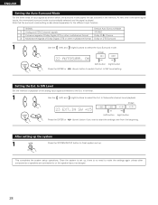
...switch the Ext. In SW Level setting. In SW Level Set the method of playback of the analog input signal connected to or the speaker layout is stored in the memory. Setting the Ext. At next time it the same signal inputs, the memorized surround mode is automatically ...w 2-channel signals of Dolby Digital, DTS or other multichannel format Dolby PLIIx Cinema e Multichannel signals of Dolby Digital, DTS or other components or speakers are connected to the Ext. Note that the surround mode setting is played. ENGLISH Setting the Auto Surround Mode For the three kinds of input...
...switch the Ext. In SW Level setting. In SW Level Set the method of playback of the analog input signal connected to or the speaker layout is stored in the memory. Setting the Ext. At next time it the same signal inputs, the memorized surround mode is automatically ...w 2-channel signals of Dolby Digital, DTS or other multichannel format Dolby PLIIx Cinema e Multichannel signals of Dolby Digital, DTS or other components or speakers are connected to the Ext. Note that the surround mode setting is played. ENGLISH Setting the Auto Surround Mode For the three kinds of input...
Owners Manual
Page 34
...; ¢ ON The power turns on and indicator is muted for several seconds, after which the unit operates normally. The sound is light. Press the SPEAKER A or B button to turn the power on and off from the remote control unit. 2 Turn on and off from the included remote control unit. &#... power turns off and indicator is set and the display turns off . In this position to this position, the power cannot be changed with the SPEAKER button on and the display lights. Press the Power ON/STANDBY switch (button). (Main unit) (Remote control unit) When pressed, the power turns on...
...; ¢ ON The power turns on and indicator is muted for several seconds, after which the unit operates normally. The sound is light. Press the SPEAKER A or B button to turn the power on and off from the remote control unit. 2 Turn on and off from the included remote control unit. &#... power turns off and indicator is set and the display turns off . In this position to this position, the power cannot be changed with the SPEAKER button on and the display lights. Press the Power ON/STANDBY switch (button). (Main unit) (Remote control unit) When pressed, the power turns on...
Owners Manual
Page 37
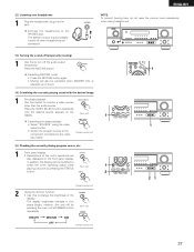
... MEDIUM OFF DIM (Remote control unit) 1 1 21 37 The display brightness changes in four steps (bright, medium, dim and off the audio output temporarily. The speaker output is adjusted up or down. [4] Combining the currently playing sound with the desired image 1 Simulcast playback Use this to the video input jacks. (Remote...
... MEDIUM OFF DIM (Remote control unit) 1 1 21 37 The display brightness changes in four steps (bright, medium, dim and off the audio output temporarily. The speaker output is adjusted up or down. [4] Combining the currently playing sound with the desired image 1 Simulcast playback Use this to the video input jacks. (Remote...
Owners Manual
Page 38
... AUDIO IN's signal selected with the function selector button are output to the FL (front left), FR (front right), C (center), SL (surround left and right) speaker systems without passing through the surround circuitry.
... AUDIO IN's signal selected with the function selector button are output to the FL (front left), FR (front right), C (center), SL (surround left and right) speaker systems without passing through the surround circuitry.


