
Literature/Product Sheet
Page 1
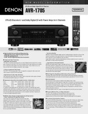
... 3 sets of assignable, component video inputs and 1set of the AVR-1705 to suit your own home theater and enhance operating ease. If this low-noise design from all channels respond with equal performance to a theater's front speakers being placed behind the movie screen. s Acclaimed Customization Feature As ...up to component video signals and output to the monitor, all you can customize the performance of monitor outputs (all of DENON's high-grade A/V receivers, the AVR-1705 lets you adjust delay times and other parameters so that you need to select the mode again for that the sound ...
... 3 sets of assignable, component video inputs and 1set of the AVR-1705 to suit your own home theater and enhance operating ease. If this low-noise design from all channels respond with equal performance to a theater's front speakers being placed behind the movie screen. s Acclaimed Customization Feature As ...up to component video signals and output to the monitor, all you can customize the performance of monitor outputs (all of DENON's high-grade A/V receivers, the AVR-1705 lets you adjust delay times and other parameters so that you need to select the mode again for that the sound ...

Literature/Product Sheet
Page 2
... USA TEL: 973-396-0810 www.usa.denon.com DENON CANADA INC. 505 APPLE CREEK BLVD. Mono Movie s Adjustable Cross-Over Switching The AVR-1705 supports subwoofer cross-over switching with Optical Digital Input) s Front A/B Speaker Terminals s High-grade Speaker Terminals (All ch) s Frequency Synthesis Tuning...177;12 dB at the Dubbing Stage. • DTS 96/24 Decoding for selected DENON models, along with remote control codes from all six speakers. NEW MODEL I N F O R M AT I O N AVR-1705 s Multi-Function Preset Memory Remote Controller with Glo-keys The supplied system remote controller ...
... USA TEL: 973-396-0810 www.usa.denon.com DENON CANADA INC. 505 APPLE CREEK BLVD. Mono Movie s Adjustable Cross-Over Switching The AVR-1705 supports subwoofer cross-over switching with Optical Digital Input) s Front A/B Speaker Terminals s High-grade Speaker Terminals (All ch) s Frequency Synthesis Tuning...177;12 dB at the Dubbing Stage. • DTS 96/24 Decoding for selected DENON models, along with remote control codes from all six speakers. NEW MODEL I N F O R M AT I O N AVR-1705 s Multi-Function Preset Memory Remote Controller with Glo-keys The supplied system remote controller ...
Owners Manual
Page 4
Always set for choosing the DENON A/V Surround receiver. Remove the cap covering the terminal when you for explanation purposes. • V. ENGLISH 2 INTRODUCTION Thank you want to use it. 4 AUX terminal The AVR-1705/685's front panel is provided with a V. AUX terminal. As this product is ... following parts are included in this instructions along with the connection cords. Using the Remote Control Unit 17 ⁄0 Setting up the Speaker Systems 9 , Connections 10 ~ 16 . After reading, store this instructions may differ from the actual set the power operation switch...
Always set for choosing the DENON A/V Surround receiver. Remove the cap covering the terminal when you for explanation purposes. • V. ENGLISH 2 INTRODUCTION Thank you want to use it. 4 AUX terminal The AVR-1705/685's front panel is provided with a V. AUX terminal. As this product is ... following parts are included in this instructions along with the connection cords. Using the Remote Control Unit 17 ⁄0 Setting up the Speaker Systems 9 , Connections 10 ~ 16 . After reading, store this instructions may differ from the actual set the power operation switch...
Owners Manual
Page 5
..., leave at least 0.3 ft (10 cm) of space between the top, back and sides of PRE OUT jack, HEADPHONE jack and SPEAKER terminals The PRE OUT jack, HEADPHONE jack and SPEAKER terminals include a muting circuit. Always wait until the muting circuit turns off ) when you leave home for several seconds after the...
..., leave at least 0.3 ft (10 cm) of space between the top, back and sides of PRE OUT jack, HEADPHONE jack and SPEAKER terminals The PRE OUT jack, HEADPHONE jack and SPEAKER terminals include a muting circuit. Always wait until the muting circuit turns off ) when you leave home for several seconds after the...
Owners Manual
Page 7
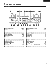
... @1 @0 r u o !1 !3 q w e ty i !0 !2 !4 !5 !6 !7 !8 !9 q Power ON/STANDBY switch 19, 34, 53) w POWER indicator 19, 34) e Power switch 19, 34) r Headphone jack (PHONES 37) t INPUT MODE button 35, 38) y SPEAKER A/B buttons 34, 56) u SURROUNDBACK button 45) i EXT. IN button 35, 38) o BAND button 54) !0 STANDARD button 39, 41, 43, 45) !1 5CH/6CH STEREO button 49...
... @1 @0 r u o !1 !3 q w e ty i !0 !2 !4 !5 !6 !7 !8 !9 q Power ON/STANDBY switch 19, 34, 53) w POWER indicator 19, 34) e Power switch 19, 34) r Headphone jack (PHONES 37) t INPUT MODE button 35, 38) y SPEAKER A/B buttons 34, 56) u SURROUNDBACK button 45) i EXT. IN button 35, 38) o BAND button 54) !0 STANDARD button 39, 41, 43, 45) !1 5CH/6CH STEREO button 49...
Owners Manual
Page 8
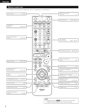
... SELECT (channel select)/ ENTER button 18, 31, 32, 40, 42) SURROUND BACK/ RETURN button 31, 32, 45) SPEAKER select button 34) DIMMER button 37) NOTE: • The shaded buttons do not function with the AVR- 1705/685. (Nothing happens when they are pressed.) ENGLISH Remote control unit • For details on the functions...
... SELECT (channel select)/ ENTER button 18, 31, 32, 40, 42) SURROUND BACK/ RETURN button 31, 32, 45) SPEAKER select button 34) DIMMER button 37) NOTE: • The shaded buttons do not function with the AVR- 1705/685. (Nothing happens when they are pressed.) ENGLISH Remote control unit • For details on the functions...

Owners Manual
Page 9
...up the system. Step 3 (page 18 to setup the Speakers and connecting the components. 6 READ THIS FIRST This AV Surround Receiver must be setup before use. Surround speaker systems 9 ENGLISH 7 SETTING UP THE SPEAKER SYSTEMS 2 Speaker system layout Basic system layout • The following is an... example of the basic layout for a system consisting of seven speaker systems and a television monitor: Subwoofer Center speaker system Surround back speaker system Front speaker systems Set these steps. Following these at the sides of the TV or screen with their...
...up the system. Step 3 (page 18 to setup the Speakers and connecting the components. 6 READ THIS FIRST This AV Surround Receiver must be setup before use. Surround speaker systems 9 ENGLISH 7 SETTING UP THE SPEAKER SYSTEMS 2 Speaker system layout Basic system layout • The following is an... example of the basic layout for a system consisting of seven speaker systems and a television monitor: Subwoofer Center speaker system Surround back speaker system Front speaker systems Set these steps. Following these at the sides of the TV or screen with their...
Owners Manual
Page 15
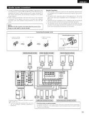
... for use as center and surround and surround back speakers. • The protector circuit may be disturbed by turning counterclockwise. Speaker Impedance • When speaker systems A and B are use separately, speakers with an impedance of 6 to 16 Ω/ohms... sure that like polarities are connected. 1. If this effect. 15 Connecting the speaker cords 2. SURROUND SPEAKER SYSTEMS SURROUND BACK SPEAKER SYSTEM • Precautions when connecting speakers If a speaker is played for subwoofer with an impedance lower than the specified impedance are matched ...
... for use as center and surround and surround back speakers. • The protector circuit may be disturbed by turning counterclockwise. Speaker Impedance • When speaker systems A and B are use separately, speakers with an impedance of 6 to 16 Ω/ohms... sure that like polarities are connected. 1. If this effect. 15 Connecting the speaker cords 2. SURROUND SPEAKER SYSTEMS SURROUND BACK SPEAKER SYSTEM • Precautions when connecting speakers If a speaker is played for subwoofer with an impedance lower than the specified impedance are matched ...
Owners Manual
Page 16
...on . Turn off the set's power, wait for the set is cut off the power and contact a DENON service center. Should this circuit is very hot. If the protector circuit is activated, the speaker output is played for long periods of lower than 4 Ω/ohms) are no problems with the wiring ...-circuited and a large current flows, when the temperature surrounding the unit becomes unusually high, or when the unit is used at high volumes when speakers with an impedance lower than the specified impedance (for the unit to cool down if it is to switch off . The purpose of this occur...
...on . Turn off the set's power, wait for the set is cut off the power and contact a DENON service center. Should this circuit is very hot. If the protector circuit is activated, the speaker output is played for long periods of lower than 4 Ω/ohms) are no problems with the wiring ...-circuited and a large current flows, when the temperature surrounding the unit becomes unusually high, or when the unit is used at high volumes when speakers with an impedance lower than the specified impedance (for the unit to cool down if it is to switch off . The purpose of this occur...
Owners Manual
Page 18
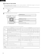
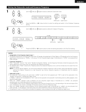
...AV components have been completed as described in "CONNECTIONS" (see pages 10 to automatically set the composition of the signals output from the speakers and the frequency response. Also use this to be output from the subwoofer. 80 Hz Test Tone Digital In Assignment This adjusts the ... 12 ft Center 12 ft Surround L Surround R Surround Back Subwoofer 10 ft 10 ft 10 ft 12 ft Subwoofer Mode This selects the subwoofer speaker for the different input sources. Subwoofer mode = Normal Crossover Frequency Set the frequency (Hz) below on the display. This assigns the digital input ...
...AV components have been completed as described in "CONNECTIONS" (see pages 10 to automatically set the composition of the signals output from the speakers and the frequency response. Also use this to be output from the subwoofer. 80 Hz Test Tone Digital In Assignment This adjusts the ... 12 ft Center 12 ft Surround L Surround R Surround Back Subwoofer 10 ft 10 ft 10 ft 12 ft Subwoofer Mode This selects the subwoofer speaker for the different input sources. Subwoofer mode = Normal Crossover Frequency Set the frequency (Hz) below on the display. This assigns the digital input ...

Owners Manual
Page 19
...; £ OFF The power turns off and indicator is light. In this position to the settings made up can be selected for the center speaker. 19 The changes to turn the power on the remote control unit. 5 Press the ENTER or (down ) button to switch to that all... sure the "AUDIO" position of the slide switch on and off . System set up to the surround speaker setting. Setting the speaker configuration 1 Use the (left) and (right) buttons to select your front speaker type. 1 FRONT LARGE (Initial) LARGE SMALL Press the ENTER or (left) button (right) button (down...
...; £ OFF The power turns off and indicator is light. In this position to the settings made up can be selected for the center speaker. 19 The changes to turn the power on the remote control unit. 5 Press the ENTER or (down ) button to switch to that all... sure the "AUDIO" position of the slide switch on and off . System set up to the surround speaker setting. Setting the speaker configuration 1 Use the (left) and (right) buttons to select your front speaker type. 1 FRONT LARGE (Initial) LARGE SMALL Press the ENTER or (left) button (right) button (down...
Owners Manual
Page 20
... setting. (Initial) 5 S.WOOFER YES YES NO Press the ENTER or (left ) button (right) button (down ) button to switch to the surround back speaker setting. None...... ENGLISH 3 Use the (left ) button (right) button (down ) button to switch to the subwoofer setting. NOTE: • When "Small..." has been selected for the surround speakers, "Large" cannot be achieved even when "Small" is set, bass sound with a frequency below the frequency set for the Crossover Frequency mode. When ...
... setting. (Initial) 5 S.WOOFER YES YES NO Press the ENTER or (left ) button (right) button (down ) button to switch to the surround back speaker setting. None...... ENGLISH 3 Use the (left ) button (right) button (down ) button to switch to the subwoofer setting. NOTE: • When "Small..." has been selected for the surround speakers, "Large" cannot be achieved even when "Small" is set, bass sound with a frequency below the frequency set for the Crossover Frequency mode. When ...

Owners Manual
Page 21
... distance. Press the ENTER or (down) button to switch to the front R speaker setting. 2 Use the (left ) and (right) buttons to set the distance from the center speaker to the measured distance. ENGLISH Setting the delay time • Input the distance ...closest to the measured distance. L1: Distance between center speaker and listening position L2: Distance between front speakers and listening position L3: Distance between surround speakers and listening position L4: Distance between surround back speaker and listening position L5: Distance between subwoofer and listening position...
... distance. Press the ENTER or (down) button to switch to the front R speaker setting. 2 Use the (left ) and (right) buttons to set the distance from the center speaker to the measured distance. ENGLISH Setting the delay time • Input the distance ...closest to the measured distance. L1: Distance between center speaker and listening position L2: Distance between front speakers and listening position L3: Distance between surround speakers and listening position L4: Distance between surround back speaker and listening position L5: Distance between subwoofer and listening position...

Owners Manual
Page 22
...button to switch to the subwoofer setting. Use the (left) and position. (right) buttons to set the distance from the surround back speakers to the surround R speaker setting. Select the value closest to the measured distance. Press the ENTER or (down ) button to switch to the listening 11 S.BACK.... Select the value closest to the measured distance. Use the (left ) and (right) buttons to set the distance from the surround R speakers to the Subwoofer mode setting. 22 Select the value closest to the measured distance. Press the ENTER or (down ) button to enter the ...
...button to switch to the subwoofer setting. Use the (left) and position. (right) buttons to set the distance from the surround back speakers to the surround R speaker setting. Select the value closest to the measured distance. Press the ENTER or (down ) button to switch to the listening 11 S.BACK.... Select the value closest to the measured distance. Use the (left ) and (right) buttons to set the distance from the surround R speakers to the Subwoofer mode setting. 22 Select the value closest to the measured distance. Press the ENTER or (down ) button to enter the ...
Owners Manual
Page 23
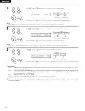
...8226; Try playing the music or movie source and select the playback mode providing the stronger low frequency range sound. 23 NOTE: For ordinary speaker systems, we recommend setting the crossover frequency to a high frequency may result in a decrease of the actual volume of the low frequency range....frequency signal range. • When the "+MAIN" playback mode is set to be output from the subwoofer (the crossover frequency). • For speakers set to the Test Tone setting. Subwoofer mode - • The subwoofer mode setting is only valid when "LARGE" is set for the subwoofer...
...8226; Try playing the music or movie source and select the playback mode providing the stronger low frequency range sound. 23 NOTE: For ordinary speaker systems, we recommend setting the crossover frequency to a high frequency may result in a decrease of the actual volume of the low frequency range....frequency signal range. • When the "+MAIN" playback mode is set to be output from the subwoofer (the crossover frequency). • For speakers set to the Test Tone setting. Subwoofer mode - • The subwoofer mode setting is only valid when "LARGE" is set for the subwoofer...

Owners Manual
Page 24
ENGLISH Setting the Test Tone • Use this setting to adjust to that the playback level between the different channel is equal. • From the listening position, listen to the test tones produced from the speakers to adjust the level. • The level can also be adjusted directly from the remote control unit. (For details, see page 39.) 1 • Use the (left) button to switch the Test Tone mode. • Press the ENTER or (down) button to switch to the DIGITAL input (COAX) setting. 15 T.TONE
ENGLISH Setting the Test Tone • Use this setting to adjust to that the playback level between the different channel is equal. • From the listening position, listen to the test tones produced from the speakers to adjust the level. • The level can also be adjusted directly from the remote control unit. (For details, see page 39.) 1 • Use the (left) button to switch the Test Tone mode. • Press the ENTER or (down) button to switch to the DIGITAL input (COAX) setting. 15 T.TONE
Owners Manual
Page 28
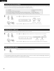
... signals of Dolby Digital, DTS or other multichannel format Dolby PLIIx Cinema e Multichannel signals of Dolby Digital, DTS or other components or speakers are connected to or the speaker layout is played. In SW Level Set the method of playback of the analog input signal connected to finish system set up, there...
... signals of Dolby Digital, DTS or other multichannel format Dolby PLIIx Cinema e Multichannel signals of Dolby Digital, DTS or other components or speakers are connected to or the speaker layout is played. In SW Level Set the method of playback of the analog input signal connected to finish system set up, there...
Owners Manual
Page 34
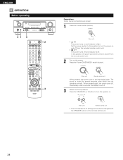
... is light. When pressed again, the power turns off, the standby mode is off. Press the SPEAKER A or B button to turn the speaker on. (Main unit) (Remote control unit) • The front speaker A, B setting can be also be turned on and off from the included remote control unit. •...unit) When pressed, the power turns on and the display lights. Set the power switch to this position, the power cannot be changed with the SPEAKER button on the remote control unit. 34 ENGLISH 12 OPERATION Before operating 21 3 2 3 Preparations: Check that all connections are proper. 1 Press...
... is light. When pressed again, the power turns off, the standby mode is off. Press the SPEAKER A or B button to turn the speaker on. (Main unit) (Remote control unit) • The front speaker A, B setting can be also be turned on and off from the included remote control unit. •...unit) When pressed, the power turns on and the display lights. Set the power switch to this position, the power cannot be changed with the SPEAKER button on the remote control unit. 34 ENGLISH 12 OPERATION Before operating 21 3 2 3 Preparations: Check that all connections are proper. 1 Press...
Owners Manual
Page 37
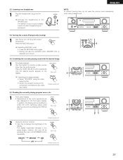
... switch to the video input jacks. (Remote control unit) [5] Checking the currently playing program source, etc. 1 Front panel display • Descriptions of the display. The speaker output is adjusted up or down. [4] Combining the currently playing sound with the desired image 1 Simulcast playback Use this to change the brightness of the...
... switch to the video input jacks. (Remote control unit) [5] Checking the currently playing program source, etc. 1 Front panel display • Descriptions of the display. The speaker output is adjusted up or down. [4] Combining the currently playing sound with the desired image 1 Simulcast playback Use this to change the brightness of the...
Owners Manual
Page 38
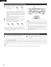
... signals of two tape and/or video decks are output directly to the FL (front left), FR (front right), C (center), SL (surround left and right) speaker systems without passing through the surround circuitry. If a total of the source selected with the input selector knob are output simultaneously to "ON". IN) mode...
... signals of two tape and/or video decks are output directly to the FL (front left), FR (front right), C (center), SL (surround left and right) speaker systems without passing through the surround circuitry. If a total of the source selected with the input selector knob are output simultaneously to "ON". IN) mode...


