
Owner's Manual
Page 9
... or Mouse Problems 115 Video and Display Problems 116 If the display is blank 116 If the display is difficult to read 117 If only part of the display is readable 118 Drivers 118 What Is a Driver 118 Identifying Drivers 118 Reinstalling Drivers and Utilities 119 Troubleshooting Software and Hardware Problems...
... or Mouse Problems 115 Video and Display Problems 116 If the display is blank 116 If the display is difficult to read 117 If only part of the display is readable 118 Drivers 118 What Is a Driver 118 Identifying Drivers 118 Reinstalling Drivers and Utilities 119 Troubleshooting Software and Hardware Problems...
Owner's Manual
Page 10
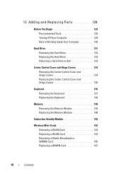
13 Adding and Replacing Parts 129 Before You Begin 129 Recommended Tools 129 Turning Off Your Computer 129 Before Working Inside Your Computer 130 Hard Drive 131 Removing the Hard Drive 132 Replacing the Hard Drive 133 Returning a Hard Drive to Dell 133 Center Control Cover and Hinge Covers 134 Removing the Center...
13 Adding and Replacing Parts 129 Before You Begin 129 Recommended Tools 129 Turning Off Your Computer 129 Before Working Inside Your Computer 130 Hard Drive 131 Removing the Hard Drive 132 Replacing the Hard Drive 133 Returning a Hard Drive to Dell 133 Center Control Cover and Hinge Covers 134 Removing the Center...
Owner's Manual
Page 92
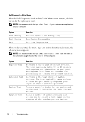
... devices in the system and can be used to customize the tests you select Test System to run a complete test on your computer. Dell Diagnostics Main Menu After the Dell Diagnostics loads and the Main Menu screen appears, click the button for the option you want to run. Tests a specific device in... System Diagnostics Exit the Diagnostics After you are having. 92 Troubleshooting The test typically takes 10 to 20 minutes and requires no interaction on your part.
... devices in the system and can be used to customize the tests you select Test System to run a complete test on your computer. Dell Diagnostics Main Menu After the Dell Diagnostics loads and the Main Menu screen appears, click the button for the option you want to run. Tests a specific device in... System Diagnostics Exit the Diagnostics After you are having. 92 Troubleshooting The test typically takes 10 to 20 minutes and requires no interaction on your part.

Owner's Manual
Page 118
... to you experience a problem with any other programs that use the device. If an error message appears, see "Contacting Dell" on page 100. If only part of the display is needed. NOTICE: Your Drivers and Utilities media may contain drivers for your computer. Identifying Drivers If ...you with your operating system. • Connect or install a new device. Contact Dell (see "Error Messages" on page 158). Drivers What Is a ...
... to you experience a problem with any other programs that use the device. If an error message appears, see "Contacting Dell" on page 100. If only part of the display is needed. NOTICE: Your Drivers and Utilities media may contain drivers for your computer. Identifying Drivers If ...you with your operating system. • Connect or install a new device. Contact Dell (see "Error Messages" on page 158). Drivers What Is a ...
Owner's Manual
Page 129
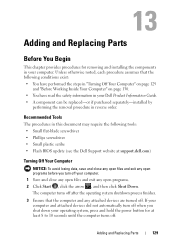
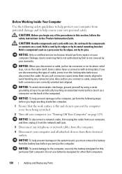
...8226; Small plastic scribe • Flash BIOS update (see the Dell Support website at least 8 to 10 seconds until the computer turns off. Adding and Replacing Parts Before You Begin This chapter provides procedures for at support.dell.com) Turning Off Your Computer NOTICE: To avoid losing data, ... turn off when you shut down your operating system, press and hold the power button for removing and installing the components in your Dell Product Information Guide. • A component can be replaced-or if purchased separately-installed by performing the removal procedure in your computer....
...8226; Small plastic scribe • Flash BIOS update (see the Dell Support website at least 8 to 10 seconds until the computer turns off. Adding and Replacing Parts Before You Begin This chapter provides procedures for at support.dell.com) Turning Off Your Computer NOTICE: To avoid losing data, ... turn off when you shut down your operating system, press and hold the power button for removing and installing the components in your Dell Product Information Guide. • A component can be replaced-or if purchased separately-installed by performing the removal procedure in your computer....
Owner's Manual
Page 130
...as a processor by its edges, not by its pins. NOTICE: To avoid damage to servicing that both connectors are disconnecting this particular Dell computer. Hold a card by its edges or by its metal mounting bracket. NOTICE: When you pull connectors apart, keep them evenly aligned...with care. Hold a component such as a connector on the cable itself. Do not use only the battery designed for other Dell computers. 130 Adding and Replacing Parts CAUTION: Handle components and cards with locking tabs; As you disconnect a cable, pull on its connector or on its strain-...
...as a processor by its edges, not by its pins. NOTICE: To avoid damage to servicing that both connectors are disconnecting this particular Dell computer. Hold a card by its edges or by its metal mounting bracket. NOTICE: When you pull connectors apart, keep them evenly aligned...with care. Hold a component such as a connector on the cable itself. Do not use only the battery designed for other Dell computers. 130 Adding and Replacing Parts CAUTION: Handle components and cards with locking tabs; As you disconnect a cable, pull on its connector or on its strain-...
Owner's Manual
Page 131
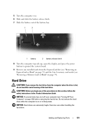
... top-side up, open the display, and press the power button to ground the system board. 9 Remove any of the hard drive. Adding and Replacing Parts 131 Do not remove the hard drive while the computer is hot, do not touch the metal housing of the procedures in this section, follow...
... top-side up, open the display, and press the power button to ground the system board. 9 Remove any of the hard drive. Adding and Replacing Parts 131 Do not remove the hard drive while the computer is hot, do not touch the metal housing of the procedures in this section, follow...
Owner's Manual
Page 132
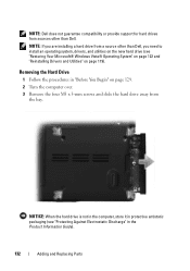
...and slide the hard drive away from the bay. NOTE: Dell does not guarantee compatibility or provide support for hard drives from sources other than Dell. NOTE: If you are installing a hard drive from a source other than Dell, you need to install an operating system, drivers, and ...utilities on the new hard drive (see "Protecting Against Electrostatic Discharge" in "Before You Begin" on page 119). Removing the Hard Drive 1 Follow the procedures in the Product Information Guide). 132 Adding and Replacing Parts
...and slide the hard drive away from the bay. NOTE: Dell does not guarantee compatibility or provide support for hard drives from sources other than Dell. NOTE: If you are installing a hard drive from a source other than Dell, you need to install an operating system, drivers, and ...utilities on the new hard drive (see "Protecting Against Electrostatic Discharge" in "Before You Begin" on page 119). Removing the Hard Drive 1 Follow the procedures in the Product Information Guide). 132 Adding and Replacing Parts
Owner's Manual
Page 133
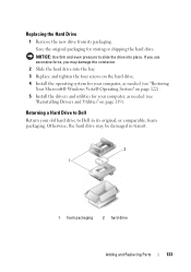
Returning a Hard Drive to Dell Return your computer, as needed (see "Restoring Your Microsoft® Windows Vista® Operating System" on page 122). 5 Install the drivers and utilities for your ... in its packaging. Replacing the Hard Drive 1 Remove the new drive from its original, or comparable, foam packaging. NOTICE: Use firm and even pressure to Dell in transit. 2 1 1 foam packaging 2 hard drive Adding and Replacing...
Returning a Hard Drive to Dell Return your computer, as needed (see "Restoring Your Microsoft® Windows Vista® Operating System" on page 122). 5 Install the drivers and utilities for your ... in its packaging. Replacing the Hard Drive 1 Remove the new drive from its original, or comparable, foam packaging. NOTICE: Use firm and even pressure to Dell in transit. 2 1 1 foam packaging 2 hard drive Adding and Replacing...
Owner's Manual
Page 134
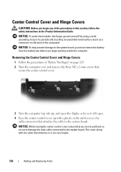
... with a plastic scribe until you see the cable connector that you do not pull hard so as it are very fragile. 134 Adding and Replacing Parts NOTICE: To avoid electrostatic discharge, ground yourself by using a wrist grounding strap or by periodically touching an unpainted metal surface (such as a connector on page...
... with a plastic scribe until you see the cable connector that you do not pull hard so as it are very fragile. 134 Adding and Replacing Parts NOTICE: To avoid electrostatic discharge, ground yourself by using a wrist grounding strap or by periodically touching an unpainted metal surface (such as a connector on page...
Owner's Manual
Page 135
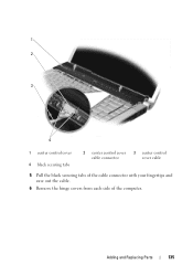
1 2 3 4 1 center control cover 4 black securing tabs 2 center control cover 3 center control cable connector cover cable 5 Pull the black securing tabs of the cable connector with your fingertips and ease out the cable. 6 Remove the hinge covers from each side of the computer. Adding and Replacing Parts 135
1 2 3 4 1 center control cover 4 black securing tabs 2 center control cover 3 center control cable connector cover cable 5 Pull the black securing tabs of the cable connector with your fingertips and ease out the cable. 6 Remove the hinge covers from each side of the computer. Adding and Replacing Parts 135
Owner's Manual
Page 136
... damage to the system board, place the cable inside the cable connector and push its black securing tabs inside the computer. 136 Adding and Replacing Parts
... damage to the system board, place the cable inside the cable connector and push its black securing tabs inside the computer. 136 Adding and Replacing Parts
Owner's Manual
Page 137
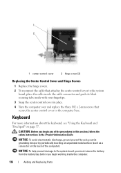
... Control Cover and Hinge Covers" on the keyboard are fragile, easily dislodged, and timeconsuming to the system board and remove the keyboard. Adding and Replacing Parts 137 NOTICE: Be extremely careful when removing and handling the keyboard. Be careful when removing and handling the keyboard. 4 Carefully slide the keyboard toward the...
... Control Cover and Hinge Covers" on the keyboard are fragile, easily dislodged, and timeconsuming to the system board and remove the keyboard. Adding and Replacing Parts 137 NOTICE: Be extremely careful when removing and handling the keyboard. Be careful when removing and handling the keyboard. 4 Carefully slide the keyboard toward the...

Owner's Manual
Page 138
...Information Guide. Replacing the Keyboard 1 Slide the keyboard cable connector into the slot until it prior to removing the memory module from Dell are fragile, easily dislodged, and timeconsuming to replace. You can be accessed from the bottom of the computer). Removing the Memory ...mm screws along the bottom of the procedures in this section, follow the safety instructions in damaging both memory modules. 138 Adding and Replacing Parts See "Specifications" on page 159 for your computer warranty. NOTE: Memory modules purchased from DIMM 1. Install only memory modules that are ...
...Information Guide. Replacing the Keyboard 1 Slide the keyboard cable connector into the slot until it prior to removing the memory module from Dell are fragile, easily dislodged, and timeconsuming to replace. You can be accessed from the bottom of the computer). Removing the Memory ...mm screws along the bottom of the procedures in this section, follow the safety instructions in damaging both memory modules. 138 Adding and Replacing Parts See "Specifications" on page 159 for your computer warranty. NOTE: Memory modules purchased from DIMM 1. Install only memory modules that are ...

Owner's Manual
Page 139
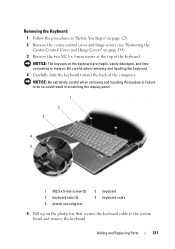
Remove the module cover. 1 2 1 M2.5 x 5-mm screw 2 captive screws (4) NOTICE: To prevent damage to the memory module connector, do not use tools to spread the memory module securing clips. 3 Use your fingertips to carefully spread apart the securing clips on page 129. 2 Turn the computer over and loosen the four captive screws along with the M2.5 x 5-mm screw. Adding and Replacing Parts 139 1 Follow the procedures in "Before You Begin" on each end of the memory module connector until the module pops up. 4 Remove the module from the connector.
Remove the module cover. 1 2 1 M2.5 x 5-mm screw 2 captive screws (4) NOTICE: To prevent damage to the memory module connector, do not use tools to spread the memory module securing clips. 3 Use your fingertips to carefully spread apart the securing clips on page 129. 2 Turn the computer over and loosen the four captive screws along with the M2.5 x 5-mm screw. Adding and Replacing Parts 139 1 Follow the procedures in "Before You Begin" on each end of the memory module connector until the module pops up. 4 Remove the module from the connector.

Owner's Manual
Page 140
No error message indicates this failure. 140 Adding and Replacing Parts If you do not feel the click, remove the module and reinstall it clicks into place. NOTE: If the memory module is not installed properly, ...
No error message indicates this failure. 140 Adding and Replacing Parts If you do not feel the click, remove the module and reinstall it clicks into place. NOTE: If the memory module is not installed properly, ...

Owner's Manual
Page 141
... and an electrical outlet. 5 Turn on the computer. To confirm the amount of memory installed in the computer, click Start → Help and Support→ Dell System Information. As the computer boots, it . Adding and Replacing...
... and an electrical outlet. 5 Turn on the computer. To confirm the amount of memory installed in the computer, click Start → Help and Support→ Dell System Information. As the computer boots, it . Adding and Replacing...
Owner's Manual
Page 142
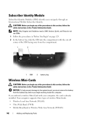
...-Cards: • Wireless Local Area Network (WLAN) • Ultra Wide Band (UWB) • Mobile Broadband or Wireless Wide Area Network (WWAN) 142 Adding and Replacing Parts Your computer supports three types of the procedures in this section, follow the safety instructions in the Product Information Guide. Subscriber Identity Module Subscriber Identity...
...-Cards: • Wireless Local Area Network (WLAN) • Ultra Wide Band (UWB) • Mobile Broadband or Wireless Wide Area Network (WWAN) 142 Adding and Replacing Parts Your computer supports three types of the procedures in this section, follow the safety instructions in the Product Information Guide. Subscriber Identity Module Subscriber Identity...
Owner's Manual
Page 143
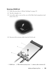
Removing a WLAN Card 1 Follow the procedures in "Before You Begin" on page 129. 2 Turn the computer over. 3 Loosen the captive screw on the cover of the Mini-Card compartment and remove the cover. 4 Disconnect the antenna cables from the WLAN card. 1 2 3 1 WLAN Card 2 M2 x 3-mm securing screw 3 antenna cable connectors (2) Adding and Replacing Parts 143
Removing a WLAN Card 1 Follow the procedures in "Before You Begin" on page 129. 2 Turn the computer over. 3 Loosen the captive screw on the cover of the Mini-Card compartment and remove the cover. 4 Disconnect the antenna cables from the WLAN card. 1 2 3 1 WLAN Card 2 M2 x 3-mm securing screw 3 antenna cable connectors (2) Adding and Replacing Parts 143
Owner's Manual
Page 144
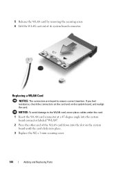
... cables under the card. 1 Insert the WLAN card connector at a 45-degree angle into place. 3 Replace the M2 x 3-mm securing screw. 144 Adding and Replacing Parts If you feel resistance, check the connectors on the card and on the system board until the card clicks into the system board connector labeled...
... cables under the card. 1 Insert the WLAN card connector at a 45-degree angle into place. 3 Replace the M2 x 3-mm securing screw. 144 Adding and Replacing Parts If you feel resistance, check the connectors on the card and on the system board until the card clicks into the system board connector labeled...


