
Owner's Manual
Page 4
... Customizing the Touch Pad 38 5 Using a Battery 39 Battery Performance 39 Checking the Battery Charge 40 Dell™ QuickSet Battery Meter 40 Microsoft® Windows® Power Meter 40 Charge Gauge 40 Low-Battery Warning 41 Conserving Battery Power 41 Power Management Modes 41 Configuring Power Management Settings 43 Charging the Battery 43 Replacing the Battery 43 Storing a Battery 43 4 Contents
... Customizing the Touch Pad 38 5 Using a Battery 39 Battery Performance 39 Checking the Battery Charge 40 Dell™ QuickSet Battery Meter 40 Microsoft® Windows® Power Meter 40 Charge Gauge 40 Low-Battery Warning 41 Conserving Battery Power 41 Power Management Modes 41 Configuring Power Management Settings 43 Charging the Battery 43 Replacing the Battery 43 Storing a Battery 43 4 Contents
Owner's Manual
Page 24
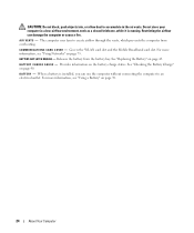
..., while it is installed, you can damage the computer or cause a fire. The computer uses fans to an electrical outlet. C O M M U N I C A T I R V E N T S - See "Checking the Battery Charge" on page 43. A I O N S C A R D C O V E R - Releases the battery from overheating. B A T T E R Y - See "Replacing the Battery" on page 40. Provides information on page 39. 24 About Your Computer For more information, see "Using...
..., while it is installed, you can damage the computer or cause a fire. The computer uses fans to an electrical outlet. C O M M U N I C A T I R V E N T S - See "Checking the Battery Charge" on page 43. A I O N S C A R D C O V E R - Releases the battery from overheating. B A T T E R Y - See "Replacing the Battery" on page 40. Provides information on page 39. 24 About Your Computer For more information, see "Using...
Owner's Manual
Page 39
.... See "Configuring Power Management Settings" on page 43 for information about the Dell warranty for your Dell computer. Using a Battery 39 NOTE: Because the battery may increase the risk of your computer. Replace the battery only with the battery installed at all times. Using a Battery Battery Performance NOTE: For information about accessing QuickSet or the Power Options Properties window...
.... See "Configuring Power Management Settings" on page 43 for information about the Dell warranty for your Dell computer. Using a Battery 39 NOTE: Because the battery may increase the risk of your computer. Replace the battery only with the battery installed at all times. Using a Battery Battery Performance NOTE: For information about accessing QuickSet or the Power Options Properties window...
Owner's Manual
Page 41
... Place the computer in standby mode or hibernate mode when you when the battery charge is in Dell QuickSet. Power Management Modes Standby Mode Standby mode conserves power by using the charge gauge on the battery as described below or by turning off the display and the hard drive after... If five lights appear, less than 80 percent of its original charge capacity remains. You can change when you should consider replacing the battery. Each light represents incremental degradation. See "Power Management Modes" on page 41 for information about standby and hibernate modes. •...
... Place the computer in standby mode or hibernate mode when you when the battery charge is in Dell QuickSet. Power Management Modes Standby Mode Standby mode conserves power by using the charge gauge on the battery as described below or by turning off the display and the hard drive after... If five lights appear, less than 80 percent of its original charge capacity remains. You can change when you should consider replacing the battery. Each light represents incremental degradation. See "Power Management Modes" on page 41 for information about standby and hibernate modes. •...

Owner's Manual
Page 43
...To access the QuickSet Power Management Wizard, double-click the icon in the taskbar. Charging the Battery NOTE: With Dell™ ExpressCharge™, the AC adapter charges a completely discharged 6-cell battery in the Power Management Wizard. • To access the Power Options Properties window, click Start... configure the power management settings on page 114. For more information about how to replace the main battery, see "Charging the Battery" on any field in a hot environment, the battery may not charge when you connect the computer to start charging if the light flashes...
...To access the QuickSet Power Management Wizard, double-click the icon in the taskbar. Charging the Battery NOTE: With Dell™ ExpressCharge™, the AC adapter charges a completely discharged 6-cell battery in the Power Management Wizard. • To access the Power Options Properties window, click Start... configure the power management settings on page 114. For more information about how to replace the main battery, see "Charging the Battery" on any field in a hot environment, the battery may not charge when you connect the computer to start charging if the light flashes...

Owner's Manual
Page 94
...CLOCK STOPPED - Connect your computer to an electrical outlet to charge the battery. M E M O R Y W R I T E / R E A D F A I L U R E A T A D D R E S S , R E A D V A L U E E X P E C T I N - Contact Dell. A chip on page 116). OPERATING SYSTEM NOT FOUND - If the message reappears, contact Dell. See "Contacting Dell" on page 141. If the hard drive is your boot device, ... operating system cannot find the hard drive. Reinstall the memory modules and, if necessary, replace them (see "Memory" on the hard drive. The reserve battery that the drive is missing an essential file.
...CLOCK STOPPED - Connect your computer to an electrical outlet to charge the battery. M E M O R Y W R I T E / R E A D F A I L U R E A T A D D R E S S , R E A D V A L U E E X P E C T I N - Contact Dell. A chip on page 116). OPERATING SYSTEM NOT FOUND - If the message reappears, contact Dell. See "Contacting Dell" on page 141. If the hard drive is your boot device, ... operating system cannot find the hard drive. Reinstall the memory modules and, if necessary, replace them (see "Memory" on the hard drive. The reserve battery that the drive is missing an essential file.

Owner's Manual
Page 95
O F - U N E X P E C T E D I N T E R R U P T I B L E . X : \ I S N O T A C C E S S I N P R O T E C T E D M O D E - Insert a disk into the connector. Replace the battery, or connect the computer to an electrical outlet. Ensure that the card is properly inserted into the drive and try again. on page 141. P R O V I D E D I E E E 1 3 9 4 D E V I N D O W S - See "Contacting Dell" on page 99. ENSURE THAT THE IEEE 1394 DEVICE IS PROPERLY INSERTED INTO THE CONNECTOR Troubleshooting 95 See "Using...
O F - U N E X P E C T E D I N T E R R U P T I B L E . X : \ I S N O T A C C E S S I N P R O T E C T E D M O D E - Insert a disk into the connector. Replace the battery, or connect the computer to an electrical outlet. Ensure that the card is properly inserted into the drive and try again. on page 141. P R O V I D E D I E E E 1 3 9 4 D E V I N D O W S - See "Contacting Dell" on page 99. ENSURE THAT THE IEEE 1394 DEVICE IS PROPERLY INSERTED INTO THE CONNECTOR Troubleshooting 95 See "Using...
Owner's Manual
Page 114
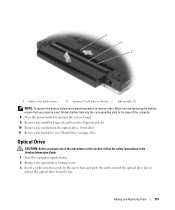
...perform the following safety guidelines to the system board, remove the main battery from the battery bay before you service the computer. 7 Remove the main battery: a Slide the battery-bay latch release on the bottom of the computer until it . b Slide the battery out toward the back of the computer and lift to a docking device... the Product Information Guide. NOTICE: Only a certified service technician should perform repairs on your docking device. See the documentation that is not authorized by Dell is connected to remove the battery from the bay. 114 Adding and Replacing Parts
...perform the following safety guidelines to the system board, remove the main battery from the battery bay before you service the computer. 7 Remove the main battery: a Slide the battery-bay latch release on the bottom of the computer until it . b Slide the battery out toward the back of the computer and lift to a docking device... the Product Information Guide. NOTICE: Only a certified service technician should perform repairs on your docking device. See the documentation that is not authorized by Dell is connected to remove the battery from the bay. 114 Adding and Replacing Parts
Owner's Manual
Page 115
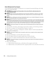
... drive from the optical drive, if installed. 11 Remove the hard drive (see "Hard Drive" on page 116). Adding and Replacing Parts 115 1 2 3 1 battery-bay latch release 2 battery (9-cell battery shown) 3 battery tabs (2) NOTE: To replace the battery, follow the safety instructions in the Product Information Guide. 1 Turn the computer upside-down. 2 Remove the optical-drive locking...
... drive from the optical drive, if installed. 11 Remove the hard drive (see "Hard Drive" on page 116). Adding and Replacing Parts 115 1 2 3 1 battery-bay latch release 2 battery (9-cell battery shown) 3 battery tabs (2) NOTE: To replace the battery, follow the safety instructions in the Product Information Guide. 1 Turn the computer upside-down. 2 Remove the optical-drive locking...
Owner's Manual
Page 121
...Align the notch in the module edge connector with the tab in the computer, click Start→ Help and Support→ Dell System Information. Adding and Replacing Parts 121 To confirm the amount of the computer). Forcing the cover to close , remove the module and reinstall it clicks... the additional memory and automatically updates the system configuration information. NOTICE: If the cover is difficult to your computer. 6 Insert the battery into the battery bay, or connect the AC adapter to close may damage your computer and an electrical outlet. 7 Reinstall the hard drive (see ...
...Align the notch in the module edge connector with the tab in the computer, click Start→ Help and Support→ Dell System Information. Adding and Replacing Parts 121 To confirm the amount of the computer). Forcing the cover to close , remove the module and reinstall it clicks... the additional memory and automatically updates the system configuration information. NOTICE: If the cover is difficult to your computer. 6 Insert the battery into the battery bay, or connect the AC adapter to close may damage your computer and an electrical outlet. 7 Reinstall the hard drive (see ...
Owner's Manual
Page 122
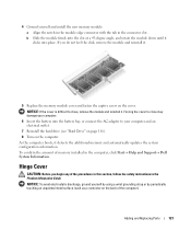
.... NOTICE: To avoid damage to left to right until the cover snaps into the indent to the right side of the computer). 122 Adding and Replacing Parts b Insert a plastic scribe into place. 1 2 1 hinge cover 2 scribe Keyboard CAUTION: Before you begin any of the procedures in this ... and remove it lies flat against your work surface. NOTICE: To help prevent damage to the system board, you must remove the battery from the battery bay before you begin working inside the computer. 1 Follow the procedures in the Product Information Guide. NOTICE: To avoid electrostatic discharge, ...
.... NOTICE: To avoid damage to left to right until the cover snaps into the indent to the right side of the computer). 122 Adding and Replacing Parts b Insert a plastic scribe into place. 1 2 1 hinge cover 2 scribe Keyboard CAUTION: Before you begin any of the procedures in this ... and remove it lies flat against your work surface. NOTICE: To help prevent damage to the system board, you must remove the battery from the battery bay before you begin working inside the computer. 1 Follow the procedures in the Product Information Guide. NOTICE: To avoid electrostatic discharge, ...
Owner's Manual
Page 123
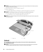
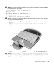
...: To help prevent damage to the system board, you must remove the battery from the keyboard connector on the system board. 1 2 3 1 screws (3) 2 keyboard 3 keyboard-connector pull-tab NOTICE: To avoid scratching the palm rest when replacing the keyboard, hook the tabs along the front edge of the keyboard into... the keyboard. Be careful when removing and handling the keyboard. c Pull on the pull-tab to release the keyboard cable from the battery bay before replacing the three screws at the top of the keyboard. b Lift the keyboard only enough to hold it up and slightly forward to allow...
...: To help prevent damage to the system board, you must remove the battery from the keyboard connector on the system board. 1 2 3 1 screws (3) 2 keyboard 3 keyboard-connector pull-tab NOTICE: To avoid scratching the palm rest when replacing the keyboard, hook the tabs along the front edge of the keyboard into... the keyboard. Be careful when removing and handling the keyboard. c Pull on the pull-tab to release the keyboard cable from the battery bay before replacing the three screws at the top of the keyboard. b Lift the keyboard only enough to hold it up and slightly forward to allow...
Owner's Manual
Page 124
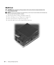
NOTICE: To help prevent damage to the system board, you must remove the main battery from the battery bay before you begin working inside the computer. 1 Follow the procedures in the Product Information Guide. WLAN Card CAUTION: Before you begin any of the procedures in this section, follow the safety instructions in "Before You Begin" on page 113. 2 Remove the hinge cover (see "Hinge Cover" on page 121). 3 Remove the keyboard (see "Keyboard" on page 122). 4 Loosen the captive screw on the communications card cover. 124 Adding and Replacing Parts
NOTICE: To help prevent damage to the system board, you must remove the main battery from the battery bay before you begin working inside the computer. 1 Follow the procedures in the Product Information Guide. WLAN Card CAUTION: Before you begin any of the procedures in this section, follow the safety instructions in "Before You Begin" on page 113. 2 Remove the hinge cover (see "Hinge Cover" on page 121). 3 Remove the keyboard (see "Keyboard" on page 122). 4 Loosen the captive screw on the communications card cover. 124 Adding and Replacing Parts
Owner's Manual
Page 128
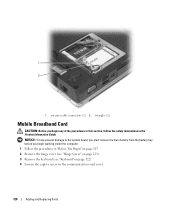
NOTICE: To help prevent damage to the system board, you must remove the main battery from the battery bay before you begin working inside the computer. 1 Follow the procedures in the Product Information Guide. 1 2 1 antenna cable connectors (2) 2 triangles (2) Mobile Broadband Card CAUTION: Before ... "Hinge Cover" on page 121). 3 Remove the keyboard (see "Keyboard" on page 122). 4 Loosen the captive screw on the communications card cover. 128 Adding and Replacing Parts
NOTICE: To help prevent damage to the system board, you must remove the main battery from the battery bay before you begin working inside the computer. 1 Follow the procedures in the Product Information Guide. 1 2 1 antenna cable connectors (2) 2 triangles (2) Mobile Broadband Card CAUTION: Before ... "Hinge Cover" on page 121). 3 Remove the keyboard (see "Keyboard" on page 122). 4 Loosen the captive screw on the communications card cover. 128 Adding and Replacing Parts
Owner's Manual
Page 134
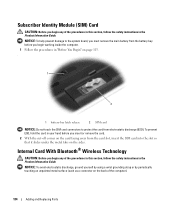
...using a wrist grounding strap or by periodically touching an unpainted metal surface (such as a connector on the back of the computer). 134 Adding and Replacing Parts Internal Card With Bluetooth® Wireless Technology CAUTION: Before you insert or remove the card. 2 With the cut-off corner on the card... latch release 2 SIM card NOTICE: Do not touch the SIM card connectors to the system board, you must remove the main battery from the battery bay before you begin any of the procedures in this section, follow the safety instructions in the Product Information Guide. NOTICE: To ...
...using a wrist grounding strap or by periodically touching an unpainted metal surface (such as a connector on the back of the computer). 134 Adding and Replacing Parts Internal Card With Bluetooth® Wireless Technology CAUTION: Before you insert or remove the card. 2 With the cut-off corner on the card... latch release 2 SIM card NOTICE: Do not touch the SIM card connectors to the system board, you must remove the main battery from the battery bay before you begin any of the procedures in this section, follow the safety instructions in the Product Information Guide. NOTICE: To ...
Owner's Manual
Page 135
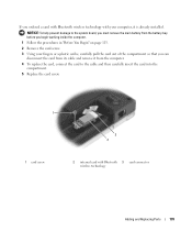
NOTICE: To help prevent damage to the system board, you must remove the main battery from the battery bay before you begin working inside the computer. 1 Follow the procedures in "Before You Begin" on page 113. 2 Remove the card screw. 3 Using your...compartment so that you ordered a card with Bluetooth wireless technology with your computer, it from the computer. 4 To replace the card, connect the card to the cable and then carefully insert the card into the compartment. 5 Replace the card screw. 1 3 2 1 card screw 2 internal card with Bluetooth 3 card connector wireless technology Adding...
NOTICE: To help prevent damage to the system board, you must remove the main battery from the battery bay before you begin working inside the computer. 1 Follow the procedures in "Before You Begin" on page 113. 2 Remove the card screw. 3 Using your...compartment so that you ordered a card with Bluetooth wireless technology with your computer, it from the computer. 4 To replace the card, connect the card to the cable and then carefully insert the card into the compartment. 5 Replace the card screw. 1 3 2 1 card screw 2 internal card with Bluetooth 3 card connector wireless technology Adding...
Owner's Manual
Page 139
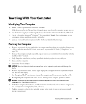
...card to the computer. • Write down the computer. • Disconnect the AC adapter. Packing the Computer • Remove any spare batteries that it offers coded identification tags. Place information such as shaving cream, colognes, perfumes, or food. Traveling With Your Computer 139 NOTICE: ...could damage the display. • Remove any extraneous items, such as possible, replace any devices installed in the module bay with the Dell TravelLite™ module. • Fully charge the main battery and any external devices attached to carry with items such as your Service Tag...
...card to the computer. • Write down the computer. • Disconnect the AC adapter. Packing the Computer • Remove any spare batteries that it offers coded identification tags. Place information such as shaving cream, colognes, perfumes, or food. Traveling With Your Computer 139 NOTICE: ...could damage the display. • Remove any extraneous items, such as possible, replace any devices installed in the module bay with the Dell TravelLite™ module. • Fully charge the main battery and any external devices attached to carry with items such as your Service Tag...
Owner's Manual
Page 189
...O operating system CD, 14, 108, 112 reinstalling, 14 reinstalling Windows XP, 108 optical drive description, 21 removing and replacing, 115 See also CD drive See also DVD drive P passwords about...standby mode, 41 surge protectors, 30 UPS, 30 power light conditions, 100 power management conserving battery power, 41 printer cable, 29 connecting, 29 Index 189 K keyboard description, 19 numeric ...Windows, 12 Service Tag, 12 lost computer, 84 M media control buttons Dell MediaDirect button, 54 description, 18 play/pause/Dell MediaDirect, 18 media memory cards blanks, 74 CardBus technology, 73, 134 ...
...O operating system CD, 14, 108, 112 reinstalling, 14 reinstalling Windows XP, 108 optical drive description, 21 removing and replacing, 115 See also CD drive See also DVD drive P passwords about...standby mode, 41 surge protectors, 30 UPS, 30 power light conditions, 100 power management conserving battery power, 41 printer cable, 29 connecting, 29 Index 189 K keyboard description, 19 numeric ...Windows, 12 Service Tag, 12 lost computer, 84 M media control buttons Dell MediaDirect button, 54 description, 18 play/pause/Dell MediaDirect, 18 media memory cards blanks, 74 CardBus technology, 73, 134 ...


