Setup Guide
Page 5
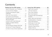
Contents Setting Up Your XPS Laptop 7 Before Setting Up Your Computer 7 Connect the AC Adapter 8 Connect the Network Cable (Optional 9 Press the Power Button 10 Set Up Microsoft Windows 11 ... Using Your XPS Laptop 22 Right View Features 22 Left View Features 26 Front View Features 27 Back View Features 28 Computer Base and Keyboard Features 30 Status Lights and Indicators 34 Disabling Battery Charging 35 Touch Pad Gestures 36 Multimedia Control Keys 38 Control Strip Features 40 Using the Optical Drive 42...
Contents Setting Up Your XPS Laptop 7 Before Setting Up Your Computer 7 Connect the AC Adapter 8 Connect the Network Cable (Optional 9 Press the Power Button 10 Set Up Microsoft Windows 11 ... Using Your XPS Laptop 22 Right View Features 22 Left View Features 26 Front View Features 27 Back View Features 28 Computer Base and Keyboard Features 30 Status Lights and Indicators 34 Disabling Battery Charging 35 Touch Pad Gestures 36 Multimedia Control Keys 38 Control Strip Features 40 Using the Optical Drive 42...
Setup Guide
Page 25
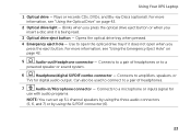
...eject button. Use to open when you insert a disc and it does not open the optical drive tray if it is being read. 3 Optical drive eject button - Using Your XPS Laptop 1 Optical drive - Connects to a pair of headphones or to a microphone or inputs signal for digital ...using the three audio connectors (5, 6, and 7) or by using the S/PDIF connector (6). 23 Opens the optical drive tray when pressed. 4 Emergency eject hole - For more information, see "Using the Optical Drive" on page 42. 5 Audio-out/Headphone connector - Connects to a powered speaker or sound system. ...
...eject button. Use to open when you insert a disc and it does not open the optical drive tray if it is being read. 3 Optical drive eject button - Using Your XPS Laptop 1 Optical drive - Connects to a pair of headphones or to a microphone or inputs signal for digital ...using the three audio connectors (5, 6, and 7) or by using the S/PDIF connector (6). 23 Opens the optical drive tray when pressed. 4 Emergency eject hole - For more information, see "Using the Optical Drive" on page 42. 5 Audio-out/Headphone connector - Connects to a powered speaker or sound system. ...

Setup Guide
Page 27
...the device stops charging. NOTE: If you to eSATA compatible storage devices (such as external hard drives or optical drives) or USB devices (such as a mouse, keyboard, printer, external drive, or MP3 player). Connects to charge USB devices when the computer is automatically shut off or... in sleep state. Using Your XPS Laptop 8 eSATA/USB combo connector with USB PowerShare - To continue ...
...the device stops charging. NOTE: If you to eSATA compatible storage devices (such as external hard drives or optical drives) or USB devices (such as a mouse, keyboard, printer, external drive, or MP3 player). Connects to charge USB devices when the computer is automatically shut off or... in sleep state. Using Your XPS Laptop 8 eSATA/USB combo connector with USB PowerShare - To continue ...

Setup Guide
Page 44
... or recording a disc. Using the Emergency Eject Hole If the optical drive tray does not eject when you press the eject button, you open or close it. Using Your XPS Laptop Using the Optical Drive CAUTION: Do not press down on the optical drive tray when you can use the emergency eject hole to open the... drive tray. Ensure that the side with print or writing is facing upward when placing...
... or recording a disc. Using the Emergency Eject Hole If the optical drive tray does not eject when you press the eject button, you open or close it. Using Your XPS Laptop Using the Optical Drive CAUTION: Do not press down on the optical drive tray when you can use the emergency eject hole to open the... drive tray. Ensure that the side with print or writing is facing upward when placing...

Setup Guide
Page 45
Using Your XPS Laptop 1 disc 2 spindle 3 optical drive tray 4 emergency eject hole 5 eject button 1 2 3 54 43
Using Your XPS Laptop 1 disc 2 spindle 3 optical drive tray 4 emergency eject hole 5 eject button 1 2 3 54 43

Setup Guide
Page 102
Index E email addresses for technical support 81 F finding more information 88 flick 46 FTP login, anonymous 81 H hard drive activity light 31 hardware problems diagnosing 67 Hardware Troubleshooter 67 help getting assistance and support 79 I Internet connection 20 100 ISP Internet Service Provider 20 M memory problems solving 61 mini-DisplayPort connector 29 Multimedia Control Keys 38 N network connection fixing 59 NVIDIA Optimus Technology 54 O Optical Drive Using 42 P power problems, solving 60
Index E email addresses for technical support 81 F finding more information 88 flick 46 FTP login, anonymous 81 H hard drive activity light 31 hardware problems diagnosing 67 Hardware Troubleshooter 67 help getting assistance and support 79 I Internet connection 20 100 ISP Internet Service Provider 20 M memory problems solving 61 mini-DisplayPort connector 29 Multimedia Control Keys 38 N network connection fixing 59 NVIDIA Optimus Technology 54 O Optical Drive Using 42 P power problems, solving 60

Service Manual
Page 4
Replacing the Mini-Card(s 23 6 Optical Drive 25 Removing the Optical Drive 25 Replacing the Optical Drive 26 7 Palm-Rest Assembly 29 Removing the Palm-Rest Assembly 29 Replacing the Palm-Rest Assembly 32 8 Power-Button Board 35 Removing the Power-Button Board 35 Replacing the Power-Button Board 36 9 Coin-Cell Battery 37 Removing the Coin-Cell Battery 37 Replacing the Coin-Cell Battery 38 10 Hard Drive 39 Removing the Hard Drive 39 Replacing the Hard Drive 41 4 Contents
Replacing the Mini-Card(s 23 6 Optical Drive 25 Removing the Optical Drive 25 Replacing the Optical Drive 26 7 Palm-Rest Assembly 29 Removing the Palm-Rest Assembly 29 Replacing the Palm-Rest Assembly 32 8 Power-Button Board 35 Removing the Power-Button Board 35 Replacing the Power-Button Board 36 9 Coin-Cell Battery 37 Removing the Coin-Cell Battery 37 Replacing the Coin-Cell Battery 38 10 Hard Drive 39 Removing the Hard Drive 39 Replacing the Hard Drive 41 4 Contents

Service Manual
Page 25
... screw that secures the optical drive to the base cover. 6 Using a plastic scribe, push the optical drive bracket to servicing that shipped with your computer. 6 Optical Drive WARNING: Before working inside your computer, read the safety information that is not authorized by Dell™ is not covered... by periodically touching an unpainted metal surface (such as a connector on page 13) before working inside the computer. Removing the Optical Drive 1 Follow the instructions in "Before You Begin" on...
... screw that secures the optical drive to the base cover. 6 Using a plastic scribe, push the optical drive bracket to servicing that shipped with your computer. 6 Optical Drive WARNING: Before working inside your computer, read the safety information that is not authorized by Dell™ is not covered... by periodically touching an unpainted metal surface (such as a connector on page 13) before working inside the computer. Removing the Optical Drive 1 Follow the instructions in "Before You Begin" on...

Service Manual
Page 26
2 1 3 4 1 optical drive 3 plastic scribe 2 screw 4 optical-drive bracket Replacing the Optical Drive 1 Follow the instructions in "Before You Begin" on page 9. 2 Remove the new optical drive from its packaging. 3 Slide the optical drive into the optical-drive bay until it is fully seated. 4 Replace the screw that secures the optical drive to the base cover. 5 Replace the memory module(s) (see "Replacing the Memory Module(s)" on...
2 1 3 4 1 optical drive 3 plastic scribe 2 screw 4 optical-drive bracket Replacing the Optical Drive 1 Follow the instructions in "Before You Begin" on page 9. 2 Remove the new optical drive from its packaging. 3 Slide the optical drive into the optical-drive bay until it is fully seated. 4 Replace the screw that secures the optical drive to the base cover. 5 Replace the memory module(s) (see "Replacing the Memory Module(s)" on...

Service Manual
Page 27
Failure to do so may result in damage to the computer. CAUTION: Before turning on the computer, replace all screws and ensure that no stray screws remain inside the computer. Optical Drive 27
Failure to do so may result in damage to the computer. CAUTION: Before turning on the computer, replace all screws and ensure that no stray screws remain inside the computer. Optical Drive 27

Service Manual
Page 28
28 Optical Drive
28 Optical Drive


