Setup Guide
Page 6
Contents Removing and Replacing the Battery 48 Software Features 50 Dell DataSafe Online Backup 51 Dell Stage (Optional 52 NVIDIA Optimus Technology 54 Free Fall Sensor 55 Dell Dock (Optional 56 Solving Problems 57 Beep Codes 57 Touch Screen Problems 58 Network Problems 59 Power Problems 60 Memory Problems 61 Lockups and Software ...
Contents Removing and Replacing the Battery 48 Software Features 50 Dell DataSafe Online Backup 51 Dell Stage (Optional 52 NVIDIA Optimus Technology 54 Free Fall Sensor 55 Dell Dock (Optional 56 Solving Problems 57 Beep Codes 57 Touch Screen Problems 58 Network Problems 59 Power Problems 60 Memory Problems 61 Lockups and Software ...

Setup Guide
Page 16
... the SIM card: 1. NOTE: Installing a mini B-CAS card into the SIM card slot. 4. Replace the battery (see "Removing and Replacing the Battery" on page 48). 5. To remove the SIM card, press and eject the SIM card. 14 Setting Up Your XPS Laptop Install the SIM Card (Optional) NOTE: Installing a SIM card is required to set...
... the SIM card: 1. NOTE: Installing a mini B-CAS card into the SIM card slot. 4. Replace the battery (see "Removing and Replacing the Battery" on page 48). 5. To remove the SIM card, press and eject the SIM card. 14 Setting Up Your XPS Laptop Install the SIM Card (Optional) NOTE: Installing a SIM card is required to set...

Setup Guide
Page 50
Align the tabs on the battery bay. 2. Slide the battery release latch to the unlock position. 3. WARNING: Before removing the battery, shut down until the battery release latch clicks. 48 Turn off the computer and turn it from the battery bay. To replace the battery: 1. Using Your XPS Laptop Removing and Replacing the Battery WARNING: Before you begin any of fire...
Align the tabs on the battery bay. 2. Slide the battery release latch to the unlock position. 3. WARNING: Before removing the battery, shut down until the battery release latch clicks. 48 Turn off the computer and turn it from the battery bay. To replace the battery: 1. Using Your XPS Laptop Removing and Replacing the Battery WARNING: Before you begin any of fire...
Setup Guide
Page 68
... boot device available - S.M.A.R.T error, possible hard drive failure. Using Support Tools CMOS checksum error - Replace the battery (see the Service Manual at support.dell.com/ manuals). CAUTION - Contact Dell (see "Contacting Dell" on page 87) for assistance. Contact Dell (see "Contacting Dell" on hard drive, the hard drive cable is loose, or no bootable device exists. •...
... boot device available - S.M.A.R.T error, possible hard drive failure. Using Support Tools CMOS checksum error - Replace the battery (see the Service Manual at support.dell.com/ manuals). CAUTION - Contact Dell (see "Contacting Dell" on page 87) for assistance. Contact Dell (see "Contacting Dell" on hard drive, the hard drive cable is loose, or no bootable device exists. •...

Service Manual
Page 3
Contents 1 Before You Begin 9 Recommended Tools 9 Turning Off Your Computer 9 Before Working Inside Your Computer 10 2 Battery 13 Removing the Battery 13 Replacing the Battery 14 3 Module Cover 15 Removing the Module Cover 15 Replacing the Module Cover 16 4 Memory Module(s 17 Removing the Memory Module(s 17 Replacing the Memory Module(s 18 5 Wireless Mini-Card(s 21 Removing the Mini-Card(s 21 Contents 3
Contents 1 Before You Begin 9 Recommended Tools 9 Turning Off Your Computer 9 Before Working Inside Your Computer 10 2 Battery 13 Removing the Battery 13 Replacing the Battery 14 3 Module Cover 15 Removing the Module Cover 15 Replacing the Module Cover 16 4 Memory Module(s 17 Removing the Memory Module(s 17 Replacing the Memory Module(s 18 5 Wireless Mini-Card(s 21 Removing the Mini-Card(s 21 Contents 3

Service Manual
Page 4
Replacing the Mini-Card(s 23 6 Optical Drive 25 Removing the Optical Drive 25 Replacing the Optical Drive 26 7 Palm-Rest Assembly 29 Removing the Palm-Rest Assembly 29 Replacing the Palm-Rest Assembly 32 8 Power-Button Board 35 Removing the Power-Button Board 35 Replacing the Power-Button Board 36 9 Coin-Cell Battery 37 Removing the Coin-Cell Battery 37 Replacing the Coin-Cell Battery 38 10 Hard Drive 39 Removing the Hard Drive 39 Replacing the Hard Drive 41 4 Contents
Replacing the Mini-Card(s 23 6 Optical Drive 25 Removing the Optical Drive 25 Replacing the Optical Drive 26 7 Palm-Rest Assembly 29 Removing the Palm-Rest Assembly 29 Replacing the Palm-Rest Assembly 32 8 Power-Button Board 35 Removing the Power-Button Board 35 Replacing the Power-Button Board 36 9 Coin-Cell Battery 37 Removing the Coin-Cell Battery 37 Replacing the Coin-Cell Battery 38 10 Hard Drive 39 Removing the Hard Drive 39 Replacing the Hard Drive 41 4 Contents

Service Manual
Page 14
1 2 1 battery 2 battery release latch Replacing the Battery CAUTION: To avoid damage to the computer, use only the battery designed for this particular Dell computer. 1 Follow the instructions in "Before You Begin" on page 9. 2 Align the tabs on the battery with the slots in the battery bay and press the battery down until it clicks into place. 14 Battery
1 2 1 battery 2 battery release latch Replacing the Battery CAUTION: To avoid damage to the computer, use only the battery designed for this particular Dell computer. 1 Follow the instructions in "Before You Begin" on page 9. 2 Align the tabs on the battery with the slots in the battery bay and press the battery down until it clicks into place. 14 Battery

Service Manual
Page 16
1 2 4 3 1 screws (3) 3 tabs (4) 2 module cover 4 base cover Replacing the Module Cover CAUTION: To avoid damage to the computer, use only the battery designed for this particular Dell computer. 1 Follow the instructions in "Before You Begin" on page 9. 2 Align the tabs on the module cover with the slots on the base cover and snap the module cover into place. 3 Tighten the three captive screws that secure the module cover to the base cover. 4 Replace the battery (see "Replacing the Battery" on page 14). 16 Module Cover
1 2 4 3 1 screws (3) 3 tabs (4) 2 module cover 4 base cover Replacing the Module Cover CAUTION: To avoid damage to the computer, use only the battery designed for this particular Dell computer. 1 Follow the instructions in "Before You Begin" on page 9. 2 Align the tabs on the module cover with the slots on the base cover and snap the module cover into place. 3 Tighten the three captive screws that secure the module cover to the base cover. 4 Replace the battery (see "Replacing the Battery" on page 14). 16 Module Cover

Service Manual
Page 19
NOTE: If the memory module is not installed properly, the computer may not boot. 3 2 1 1 tab 3 memory-module connector 2 notch 4 Replace the module cover (see "Replacing the Module Cover" on page 16). 5 Replace the battery (see "Replacing the Battery" on page 14). 6 Connect the AC adapter to your computer and an electrical outlet. 7 Turn on the computer. As...
NOTE: If the memory module is not installed properly, the computer may not boot. 3 2 1 1 tab 3 memory-module connector 2 notch 4 Replace the module cover (see "Replacing the Module Cover" on page 16). 5 Replace the battery (see "Replacing the Battery" on page 14). 6 Connect the AC adapter to your computer and an electrical outlet. 7 Turn on the computer. As...
Service Manual
Page 24
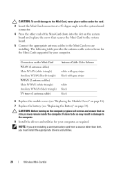
... cables under the card. 3 Insert the Mini-Card connector at a 45-degree angle into the system-board connector. 4 Press the other than Dell, you are installing. Connectors on the Mini-Card WLAN (2 antenna cables) Main WLAN (white triangle) Auxiliary WLAN (black triangle) WWAN (2 antenna...Cable Color Scheme white with gray stripe black with gray stripe white black black 6 Replace the module cover (see "Replacing the Module Cover" on page 16). 7 Replace the battery (see "Replacing the Battery" on the computer, replace all screws and ensure that secures the Mini-Card to the system board. 5 ...
... cables under the card. 3 Insert the Mini-Card connector at a 45-degree angle into the system-board connector. 4 Press the other than Dell, you are installing. Connectors on the Mini-Card WLAN (2 antenna cables) Main WLAN (white triangle) Auxiliary WLAN (black triangle) WWAN (2 antenna...Cable Color Scheme white with gray stripe black with gray stripe white black black 6 Replace the module cover (see "Replacing the Module Cover" on page 16). 7 Replace the battery (see "Replacing the Battery" on the computer, replace all screws and ensure that secures the Mini-Card to the system board. 5 ...

Service Manual
Page 26
... 2 screw 4 optical-drive bracket Replacing the Optical Drive 1 Follow the instructions in "Before You Begin" on page 9. 2 Remove the new optical drive from its packaging. 3 Slide the optical drive into the optical-drive bay until it is fully seated. 4 Replace the screw that secures the optical ...drive to the base cover. 5 Replace the memory module(s) (see "Replacing the Memory Module(s)" on page 18). 6 Replace the module cover (see "Replacing the Module Cover" on page 16). 7 Replace the battery (see "Replacing the Battery" on page 14)....
... 2 screw 4 optical-drive bracket Replacing the Optical Drive 1 Follow the instructions in "Before You Begin" on page 9. 2 Remove the new optical drive from its packaging. 3 Slide the optical drive into the optical-drive bay until it is fully seated. 4 Replace the screw that secures the optical ...drive to the base cover. 5 Replace the memory module(s) (see "Replacing the Memory Module(s)" on page 18). 6 Replace the module cover (see "Replacing the Module Cover" on page 16). 7 Replace the battery (see "Replacing the Battery" on page 14)....

Service Manual
Page 32
1 2 3 1 power-button cable connector 3 palm-rest assembly 2 touch-pad cable connector Replacing the Palm-Rest Assembly 1 Follow the instructions in "Before You Begin" on page 9. 2 Slide the touch-pad cable and the power button cable into the ... assembly with the slots on the top cover and gently snap the palm-rest assembly into place. 4 Close the display and turn the computer over. 5 Replace the screw that secures the palm-rest assembly to the base cover. 6 Replace the battery (see "Replacing the Battery" on page 14). 32 Palm-Rest Assembly
1 2 3 1 power-button cable connector 3 palm-rest assembly 2 touch-pad cable connector Replacing the Palm-Rest Assembly 1 Follow the instructions in "Before You Begin" on page 9. 2 Slide the touch-pad cable and the power button cable into the ... assembly with the slots on the top cover and gently snap the palm-rest assembly into place. 4 Close the display and turn the computer over. 5 Replace the screw that secures the palm-rest assembly to the base cover. 6 Replace the battery (see "Replacing the Battery" on page 14). 32 Palm-Rest Assembly

Service Manual
Page 36
CAUTION: Before turning on the computer, replace all screws and ensure that secure the power-button board to the palm-rest assembly. 3 Slide the power-button cable into the connector on the ... screws that no stray screws remain inside the computer. 3 1 2 1 power-button board 3 screws (2) 2 power-button cable connector Replacing the Power-Button Board 1 Follow the instructions in damage to secure the power-button cable. 4 Replace the palm-rest assembly (see "Replacing the Palm-Rest Assembly" on page 32). 5 Replace the battery (see "Replacing the Battery" on page 14).
CAUTION: Before turning on the computer, replace all screws and ensure that secure the power-button board to the palm-rest assembly. 3 Slide the power-button cable into the connector on the ... screws that no stray screws remain inside the computer. 3 1 2 1 power-button board 3 screws (2) 2 power-button cable connector Replacing the Power-Button Board 1 Follow the instructions in damage to secure the power-button cable. 4 Replace the palm-rest assembly (see "Replacing the Palm-Rest Assembly" on page 32). 5 Replace the battery (see "Replacing the Battery" on page 14).

Service Manual
Page 38
Failure to do so may result in "Before You Begin" on page 9. 2 With the positive side facing up, snap the coin-cell battery into the battery socket on the system board. 3 Replace the palm-rest assembly (see "Replacing the Palm-Rest Assembly" on page 32). 4 Replace the battery (see "Replacing the Battery" on the computer, replace all screws and ensure that no stray screws remain inside the computer. CAUTION: Before turning on page 14). 2 1 1 coin-cell battery 2 plastic scribe Replacing the Coin-Cell Battery 1 Follow the instructions in damage to the computer. 38 Coin-Cell Battery
Failure to do so may result in "Before You Begin" on page 9. 2 With the positive side facing up, snap the coin-cell battery into the battery socket on the system board. 3 Replace the palm-rest assembly (see "Replacing the Palm-Rest Assembly" on page 32). 4 Replace the battery (see "Replacing the Battery" on the computer, replace all screws and ensure that no stray screws remain inside the computer. CAUTION: Before turning on page 14). 2 1 1 coin-cell battery 2 plastic scribe Replacing the Coin-Cell Battery 1 Follow the instructions in damage to the computer. 38 Coin-Cell Battery

Service Manual
Page 42
Failure to do so may result in damage to the computer base. 8 Replace the palm-rest assembly (see "Replacing the Palm-Rest Assembly" on page 32). 9 Replace the battery (see "Replacing the Battery" on the computer, replace all screws and ensure that no stray screws remain inside the computer. 7 Replace the four screws that secure the hard-drive assembly to the computer. 42 Hard Drive CAUTION: Before turning on page 14).
Failure to do so may result in damage to the computer base. 8 Replace the palm-rest assembly (see "Replacing the Palm-Rest Assembly" on page 32). 9 Replace the battery (see "Replacing the Battery" on the computer, replace all screws and ensure that no stray screws remain inside the computer. 7 Replace the four screws that secure the hard-drive assembly to the computer. 42 Hard Drive CAUTION: Before turning on page 14).

Service Manual
Page 47
CAUTION: Before turning on page 14). Failure to do so may result in damage to the computer. Keyboard 47 6 Replace the palm-rest assembly (see "Replacing the Palm-Rest Assembly" on page 32). 7 Replace the battery (see "Replacing the Battery" on the computer, replace all screws and ensure that no stray screws remain inside the computer.
CAUTION: Before turning on page 14). Failure to do so may result in damage to the computer. Keyboard 47 6 Replace the palm-rest assembly (see "Replacing the Palm-Rest Assembly" on page 32). 7 Replace the battery (see "Replacing the Battery" on the computer, replace all screws and ensure that no stray screws remain inside the computer.

Service Manual
Page 53
...the instructions in damage to the connectors on the Mini-Card. 13 Replace the memory module(s) (see "Replacing the Memory Module(s)" on page 18). 14 Replace the module cover (see "Replacing the Module Cover" on page 16). 15 Replace the battery (see "Removing the Display Assembly" on page 14). Display Bezel Removing...cables to the computer. Failure to do so may result in "Before You Begin" on page 9. 2 Remove the display assembly (see "Replacing the Battery" on page 49). 3 Push the display bezel outwards to release it from the tabs that no stray screws remain inside the computer. Display...
...the instructions in damage to the connectors on the Mini-Card. 13 Replace the memory module(s) (see "Replacing the Memory Module(s)" on page 18). 14 Replace the module cover (see "Replacing the Module Cover" on page 16). 15 Replace the battery (see "Removing the Display Assembly" on page 14). Display Bezel Removing...cables to the computer. Failure to do so may result in "Before You Begin" on page 9. 2 Remove the display assembly (see "Replacing the Battery" on page 49). 3 Push the display bezel outwards to release it from the tabs that no stray screws remain inside the computer. Display...

Service Manual
Page 63
CAUTION: Before turning on page 14). Failure to do so may result in damage to the computer. 8 Replace the palm-rest assembly (see "Replacing the Palm-Rest Assembly" on page 32). 9 Replace the memory module(s) (see "Replacing the Memory Module(s)" on page 18). 10 Replace the module cover (see "Replacing the Module Cover" on page 16). 11 Replace the battery (see "Replacing the Battery" on the computer, replace all screws and ensure that no stray screws remain inside the computer. Camera Module 63
CAUTION: Before turning on page 14). Failure to do so may result in damage to the computer. 8 Replace the palm-rest assembly (see "Replacing the Palm-Rest Assembly" on page 32). 9 Replace the memory module(s) (see "Replacing the Memory Module(s)" on page 18). 10 Replace the module cover (see "Replacing the Module Cover" on page 16). 11 Replace the battery (see "Replacing the Battery" on the computer, replace all screws and ensure that no stray screws remain inside the computer. Camera Module 63

Service Manual
Page 69
... USB Board" on page 88). 5 Replace the AC-adapter connector (see "Replacing the AC-Adapter Connector" on page 84). 6 Replace the Bluetooth card (see "Replacing the Bluetooth Card" on page 80). 7 Replace the system board (see "Replacing the System Board" on page 105). 8 Replace the heat sink (see "Replacing the Battery" on the computer, replace all screws and ensure that...
... USB Board" on page 88). 5 Replace the AC-adapter connector (see "Replacing the AC-Adapter Connector" on page 84). 6 Replace the Bluetooth card (see "Replacing the Bluetooth Card" on page 80). 7 Replace the system board (see "Replacing the System Board" on page 105). 8 Replace the heat sink (see "Replacing the Battery" on the computer, replace all screws and ensure that...

Service Manual
Page 73
Failure to do so may result in damage to the computer. Processor Fan 73 CAUTION: Before turning on page 14). 7 Replace the palm-rest assembly (see "Replacing the Palm-Rest Assembly" on page 32). 8 Replace the memory module(s) (see "Replacing the Memory Module(s)" on page 18). 9 Replace the module cover (see "Replacing the Module Cover" on page 16). 10 Replace the battery (see "Replacing the Battery" on the computer, replace all screws and ensure that no stray screws remain inside the computer.
Failure to do so may result in damage to the computer. Processor Fan 73 CAUTION: Before turning on page 14). 7 Replace the palm-rest assembly (see "Replacing the Palm-Rest Assembly" on page 32). 8 Replace the memory module(s) (see "Replacing the Memory Module(s)" on page 18). 9 Replace the module cover (see "Replacing the Module Cover" on page 16). 10 Replace the battery (see "Replacing the Battery" on the computer, replace all screws and ensure that no stray screws remain inside the computer.


