Setup Guide
Page 21
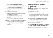
Enter the security code that shipped with your computer. 4. Setting Up Your XPS Laptop Set Up the TV Tuner (Optional) NOTE: Availability of the TV tuner may vary by region. Select your computer (Japan only). 2. Follow the instructions ... display, see the documentation that appears on your TV. The Intel Wireless Display window appears. 2. To set up the TV tuner: 1. Select Connect to the antenna-in connector on your computer. 3. Click Start → All Programs→ Windows Media Center→ Tasks→ Settings→ TV. 5. Turn on the screen. 19...
Enter the security code that shipped with your computer. 4. Setting Up Your XPS Laptop Set Up the TV Tuner (Optional) NOTE: Availability of the TV tuner may vary by region. Select your computer (Japan only). 2. Follow the instructions ... display, see the documentation that appears on your TV. The Intel Wireless Display window appears. 2. To set up the TV tuner: 1. Select Connect to the antenna-in connector on your computer. 3. Click Start → All Programs→ Windows Media Center→ Tasks→ Settings→ TV. 5. Turn on the screen. 19...
Setup Guide
Page 31
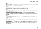
...Before you are using the TV tuner card (optional). 5 AC adapter connector - Connects to an external antenna (included) or coaxial cable (adapter included) to view programs using a wired network. 4 Antenna-in connector (on your computer to a network or a broadband device if you buy a security cable... cable to USB devices, such as a mouse, keyboard, printer, external drive, or MP3 player. 7 Security cable slot - Using Your XPS Laptop 1 Mini-DisplayPort connector - Digital interface standard connector that it fits into the security cable slot on supported models) -
...Before you are using the TV tuner card (optional). 5 AC adapter connector - Connects to an external antenna (included) or coaxial cable (adapter included) to view programs using a wired network. 4 Antenna-in connector (on your computer to a network or a broadband device if you buy a security cable... cable to USB devices, such as a mouse, keyboard, printer, external drive, or MP3 player. 7 Security cable slot - Using Your XPS Laptop 1 Mini-DisplayPort connector - Digital interface standard connector that it fits into the security cable slot on supported models) -

Setup Guide
Page 93
... 4-pin USB 3.0-compliant connectors MiniDisplayPort one 20-pin connector eSATA one 7-pin/4-pin eSATA/ USB combo connector with PowerShare Media Card Reader one 9-in-1 slot Antenna-in connector (optional) one MCX connector 91 Memory Memory type 1066 MHz/1333 MHz SODIMM DDR3 NOTE: For instructions on upgrading the memory, see the...
... 4-pin USB 3.0-compliant connectors MiniDisplayPort one 20-pin connector eSATA one 7-pin/4-pin eSATA/ USB combo connector with PowerShare Media Card Reader one 9-in-1 slot Antenna-in connector (optional) one MCX connector 91 Memory Memory type 1066 MHz/1333 MHz SODIMM DDR3 NOTE: For instructions on upgrading the memory, see the...

Service Manual
Page 22
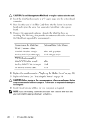
NOTE: Your computer can only support either a WWAN Mini-Card or a TV tuner module in the full Mini-Card slot at a time. 4 3 2 1 1 antenna cables (2) 3 screw 2 Mini-Card 4 system-board connector 6 Lift the Mini-Card(s) out of the system-board connector. 22 Wireless Mini-Card(s) 4 Disconnect the antenna cables from the Mini-Card(s). 5 Remove the screw that secures the Mini-Card to the system board.
NOTE: Your computer can only support either a WWAN Mini-Card or a TV tuner module in the full Mini-Card slot at a time. 4 3 2 1 1 antenna cables (2) 3 screw 2 Mini-Card 4 system-board connector 6 Lift the Mini-Card(s) out of the system-board connector. 22 Wireless Mini-Card(s) 4 Disconnect the antenna cables from the Mini-Card(s). 5 Remove the screw that secures the Mini-Card to the system board.
Service Manual
Page 24
...you are installing a communication card from a source other end of the Mini-Card down into the system-board connector. 4 Press the other than Dell, you are installing. NOTE: If you must install the appropriate drivers and utilities. 24 Wireless Mini-Card(s) CAUTION: Before turning on page 14).... the Battery" on the computer, replace all screws and ensure that secures the Mini-Card to the system board. 5 Connect the appropriate antenna cables to the computer. 8 Install the drivers and utilities for the Mini-Cards supported by your computer, as required. The following table provides ...
...you are installing a communication card from a source other end of the Mini-Card down into the system-board connector. 4 Press the other than Dell, you are installing. NOTE: If you must install the appropriate drivers and utilities. 24 Wireless Mini-Card(s) CAUTION: Before turning on page 14).... the Battery" on the computer, replace all screws and ensure that secures the Mini-Card to the system board. 5 Connect the appropriate antenna cables to the computer. 8 Install the drivers and utilities for the Mini-Cards supported by your computer, as required. The following table provides ...

Service Manual
Page 49
... your warranty. CAUTION: To help prevent damage to the system board, remove the main battery (see the Regulatory Compliance Homepage at www.dell.com/regulatory_compliance. Damage due to the base cover. Display 49 Display Assembly Removing the Display Assembly 1 Follow the instructions in "Before You...the Mini-Card antenna cables and remove them from the routing guides on your computer. CAUTION: Only a certified service technician should perform repairs on base cover. 7 Remove the two screws that secure the display assembly to servicing that is not authorized by Dell™ is ...
... your warranty. CAUTION: To help prevent damage to the system board, remove the main battery (see the Regulatory Compliance Homepage at www.dell.com/regulatory_compliance. Damage due to the base cover. Display 49 Display Assembly Removing the Display Assembly 1 Follow the instructions in "Before You...the Mini-Card antenna cables and remove them from the routing guides on your computer. CAUTION: Only a certified service technician should perform repairs on base cover. 7 Remove the two screws that secure the display assembly to servicing that is not authorized by Dell™ is ...

Service Manual
Page 50
NOTE: The digitizer board is optional and may not be present in your computer. 50 Display 1 2 1 antenna cables 2 base cover CAUTION: Be extremely careful when opening the display to prevent damaging the display assembly. 8 Remove the palm-rest assembly (see "Removing the ...
NOTE: The digitizer board is optional and may not be present in your computer. 50 Display 1 2 1 antenna cables 2 base cover CAUTION: Be extremely careful when opening the display to prevent damaging the display assembly. 8 Remove the palm-rest assembly (see "Removing the ...

Service Manual
Page 51
13 Loosen the captive screw that secures the display grounding cable. 3 1 2 1 captive screw 3 digitizer board cable 2 display cable connector 14 Note the routing of the display cable and remove the cable from the routing guides. 15 Note the routing of the Mini-Card antenna cables and remove them from the routing guides on the top cover. 16 Gently pull the antenna cables up from the bottom of the computer through the slot on the top cover. 17 Remove the four screws that secure the display assembly to the computer base. Display 51
13 Loosen the captive screw that secures the display grounding cable. 3 1 2 1 captive screw 3 digitizer board cable 2 display cable connector 14 Note the routing of the display cable and remove the cable from the routing guides. 15 Note the routing of the Mini-Card antenna cables and remove them from the routing guides on the top cover. 16 Gently pull the antenna cables up from the bottom of the computer through the slot on the top cover. 17 Remove the four screws that secure the display assembly to the computer base. Display 51

Service Manual
Page 52
1 2 3 5 4 1 display assembly 3 display cable 5 antenna cables 2 screws (4) 4 top cover 18 Lift the display assembly off the computer base. Replacing the Display Assembly 1 Follow the instructions in "Before You Begin" on ...
1 2 3 5 4 1 display assembly 3 display cable 5 antenna cables 2 screws (4) 4 top cover 18 Lift the display assembly off the computer base. Replacing the Display Assembly 1 Follow the instructions in "Before You Begin" on ...

Service Manual
Page 53
Display Bezel Removing the Display Bezel CAUTION: The display bezel is extremely fragile. 6 Route the antenna cables through the routing guides on the top cover. 7 Slide the antenna cables to the bottom of the display bezel off the back cover. 5 Lift the display bezel off the display assembly. CAUTION..."Replacing the Keyboard" on page 46). 9 Replace the palm-rest assembly (see "Replacing the Battery" on the base cover. 12 Connect the antenna cables to the computer. Be careful when removing it to prevent damaging the bezel. 1 Follow the instructions in damage to the connectors on the ...
Display Bezel Removing the Display Bezel CAUTION: The display bezel is extremely fragile. 6 Route the antenna cables through the routing guides on the top cover. 7 Slide the antenna cables to the bottom of the display bezel off the back cover. 5 Lift the display bezel off the display assembly. CAUTION..."Replacing the Keyboard" on page 46). 9 Replace the palm-rest assembly (see "Replacing the Battery" on the base cover. 12 Connect the antenna cables to the computer. Be careful when removing it to prevent damaging the bezel. 1 Follow the instructions in damage to the connectors on the ...

Service Manual
Page 56
8 Note the routing of the antenna cables and remove them from the routing guide on the right display hinge. 9 Note the routing of the display cable and remove it from the routing guide on the left display hinge. 5 4 1 2 3 1 display panel 3 display cable 5 antenna cables 2 screws (12) 4 digitizer board 10 Lift the display panel off the display back cover. 56 Display
8 Note the routing of the antenna cables and remove them from the routing guide on the right display hinge. 9 Note the routing of the display cable and remove it from the routing guide on the left display hinge. 5 4 1 2 3 1 display panel 3 display cable 5 antenna cables 2 screws (12) 4 digitizer board 10 Lift the display panel off the display back cover. 56 Display

Service Manual
Page 57
... 54). 5 Turn the display panel over the display back cover. 3 Route the display cable through the routing guide on the left display hinge. 4 Route the antenna cables through the routing guide on the right display hinge. 5 Replace the ten screws that secure the display panel to the display back cover. 6 Replace...
... 54). 5 Turn the display panel over the display back cover. 3 Route the display cable through the routing guide on the left display hinge. 4 Route the antenna cables through the routing guide on the right display hinge. 5 Replace the ten screws that secure the display panel to the display back cover. 6 Replace...


