Setup Guide
Page 6
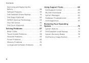
... Screen Problems 58 Network Problems 59 Power Problems 60 Memory Problems 61 Lockups and Software Problems 62 Using Support Tools 64 Dell Support Center 64 My Dell Downloads 65 System Messages 65 Hardware Troubleshooter 67 Dell Diagnostics 67 Restoring Your Operating System 72 System Restore 73 Dell DataSafe Local Backup 74 System Recovery Media 76...
... Screen Problems 58 Network Problems 59 Power Problems 60 Memory Problems 61 Lockups and Software Problems 62 Using Support Tools 64 Dell Support Center 64 My Dell Downloads 65 System Messages 65 Hardware Troubleshooter 67 Dell Diagnostics 67 Restoring Your Operating System 72 System Restore 73 Dell DataSafe Local Backup 74 System Recovery Media 76...

Setup Guide
Page 29
Blanks protect unused slots from other particles. Save the blank for use when no media card is installed in the media card slot. blanks from dust and other computers may not fit your computer. 27 For the supported memory cards, see "Specifications" on memory cards. Provides a fast and convenient way to view and share digital photos, music, videos, and documents stored on page 92. NOTE: Your computer ships with a plastic blank installed in the slot; Front View Features Using Your XPS Laptop 1 1 9-in-1 Media Card Reader -
Blanks protect unused slots from other particles. Save the blank for use when no media card is installed in the media card slot. blanks from dust and other computers may not fit your computer. 27 For the supported memory cards, see "Specifications" on memory cards. Provides a fast and convenient way to view and share digital photos, music, videos, and documents stored on page 92. NOTE: Your computer ships with a plastic blank installed in the slot; Front View Features Using Your XPS Laptop 1 1 9-in-1 Media Card Reader -
Setup Guide
Page 59
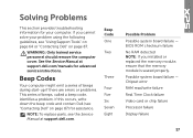
...Only trained service personnel should remove the computer cover. If this occurs, write down the beep code and contact Dell (see the Service Manual at support.dell.com/manuals for assistance. BIOS ROM checksum failure No RAM detected NOTE: If you cannot solve your computer. ...Six Seven Eight Possible Problem Possible system board failure - If you installed or replaced the memory module, ensure that the memory module is seated properly. See the Service Manual at support.dell.com. NOTE: To replace parts, see "Contacting Dell" on page 87. Possible system board failure -
...Only trained service personnel should remove the computer cover. If this occurs, write down the beep code and contact Dell (see the Service Manual at support.dell.com/manuals for assistance. BIOS ROM checksum failure No RAM detected NOTE: If you cannot solve your computer. ...Six Seven Eight Possible Problem Possible system board failure - If you installed or replaced the memory module, ensure that the memory module is seated properly. See the Service Manual at support.dell.com. NOTE: To replace parts, see "Contacting Dell" on page 87. Possible system board failure -
Setup Guide
Page 63
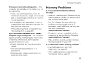
... If the power light is creating interference by interrupting or blocking other memory problems - • Run Dell Diagnostics (see "Dell Diagnostics" on page 67). • If the problem persists, contact Dell (see "Contacting Dell" on your computer - Memory Problems If you receive an insufficient memory message - • Save and close any open files and exit any open...
... If the power light is creating interference by interrupting or blocking other memory problems - • Run Dell Diagnostics (see "Dell Diagnostics" on page 67). • If the problem persists, contact Dell (see "Contacting Dell" on your computer - Memory Problems If you receive an insufficient memory message - • Save and close any open files and exit any open...
Setup Guide
Page 70
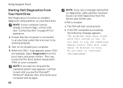
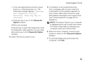
... completes successfully, the following message appears : "No problems have been found , run the remaining memory tests? This will start running tests. When the DELL™ logo appears, press immediately. Using Support Tools Starting Dell Diagnostics From Your Hard Drive Dell Diagnostics is located on a hidden diagnostic utility partition on your computer and try again...
... completes successfully, the following message appears : "No problems have been found , run the remaining memory tests? This will start running tests. When the DELL™ logo appears, press immediately. Using Support Tools Starting Dell Diagnostics From Your Hard Drive Dell Diagnostics is located on a hidden diagnostic utility partition on your computer and try again...
Setup Guide
Page 71
... on page 87) for your computer is not invoked: Press any key to start Dell Diagnostics from the diagnostic utility partition on your hard drive and to go to the... 5. The Service Tag helps you identify your screen. To exit Dell Diagnostics and restart the computer, click Exit. 69 If you contact Dell. 6. Select the test you want to the Choose An Option ...message with an error code and a description of each test screen. The following message appears: "Booting Dell Diagnostic Utility Partition. Press any key to the Choose An Option window. 4. Using Support Tools c. Press...
... on page 87) for your computer is not invoked: Press any key to start Dell Diagnostics from the diagnostic utility partition on your hard drive and to go to the... 5. The Service Tag helps you identify your screen. To exit Dell Diagnostics and restart the computer, click Exit. 69 If you contact Dell. 6. Select the test you want to the Choose An Option ...message with an error code and a description of each test screen. The following message appears: "Booting Dell Diagnostic Utility Partition. Press any key to the Choose An Option window. 4. Using Support Tools c. Press...
Setup Guide
Page 92
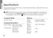
... the About Your System section in the notification area of your computer. Computer Model Dell™ XPS™ L501X Computer Information System chipset Mobile Intel® 5 series express chipset HM57 Processor type ...Intel Core™ i3 Intel Core i5 Intel Core i7 Intel Pentium® 90 Memory Memory module connector Memory module capacities Minimum memory Maximum memory two user-accessible SODIMM connectors 1 GB, 2 GB, and 4 GB 2 GB 8 GB To launch the Dell...
... the About Your System section in the notification area of your computer. Computer Model Dell™ XPS™ L501X Computer Information System chipset Mobile Intel® 5 series express chipset HM57 Processor type ...Intel Core™ i3 Intel Core i5 Intel Core i7 Intel Pentium® 90 Memory Memory module connector Memory module capacities Minimum memory Maximum memory two user-accessible SODIMM connectors 1 GB, 2 GB, and 4 GB 2 GB 8 GB To launch the Dell...

Setup Guide
Page 93
... MHz/1333 MHz SODIMM DDR3 NOTE: For instructions on upgrading the memory, see the Service Manual at support.dell.com/manuals. Connectors Audio one microphone-in connector, one stereo headphones/speakers connector NOTE: You can also use the connectors to set up 5.1 channel speakers S/...
... MHz/1333 MHz SODIMM DDR3 NOTE: For instructions on upgrading the memory, see the Service Manual at support.dell.com/manuals. Connectors Audio one microphone-in connector, one stereo headphones/speakers connector NOTE: You can also use the connectors to set up 5.1 channel speakers S/...

Setup Guide
Page 94
... Secure Digital Input Output (SDIO) Secure Digital High Capacity (SDHC) Secure Digital eXtended Capacity (SDXC) Memory Stick Memory Stick PRO MSXC Memory Card MultiMedia Card (MMC) xD-Picture Card Camera Camera resolution 2.0 megapixel HD Video resolution 1280 x 720 92 Communications Modem (optional) external V.92 56 K USB modem ...
... Secure Digital Input Output (SDIO) Secure Digital High Capacity (SDHC) Secure Digital eXtended Capacity (SDXC) Memory Stick Memory Stick PRO MSXC Memory Card MultiMedia Card (MMC) xD-Picture Card Camera Camera resolution 2.0 megapixel HD Video resolution 1280 x 720 92 Communications Modem (optional) external V.92 56 K USB modem ...

Setup Guide
Page 95
Video Integrated Video Controller Video Memory Discrete Video Controller Video Memory Display Type Intel HD Graphics up to 256 MB NVIDIA GeForce GT 420M NVIDIA GeForce GT 435M 1 GB/2 GB DDR3 15.6-inch HD WLED, TrueLife ...
Video Integrated Video Controller Video Memory Discrete Video Controller Video Memory Display Type Intel HD Graphics up to 256 MB NVIDIA GeForce GT 420M NVIDIA GeForce GT 435M 1 GB/2 GB DDR3 15.6-inch HD WLED, TrueLife ...

Setup Guide
Page 102
Index E email addresses for technical support 81 F finding more information 88 flick 46 FTP login, anonymous 81 H hard drive activity light 31 hardware problems diagnosing 67 Hardware Troubleshooter 67 help getting assistance and support 79 I Internet connection 20 100 ISP Internet Service Provider 20 M memory problems solving 61 mini-DisplayPort connector 29 Multimedia Control Keys 38 N network connection fixing 59 NVIDIA Optimus Technology 54 O Optical Drive Using 42 P power problems, solving 60
Index E email addresses for technical support 81 F finding more information 88 flick 46 FTP login, anonymous 81 H hard drive activity light 31 hardware problems diagnosing 67 Hardware Troubleshooter 67 help getting assistance and support 79 I Internet connection 20 100 ISP Internet Service Provider 20 M memory problems solving 61 mini-DisplayPort connector 29 Multimedia Control Keys 38 N network connection fixing 59 NVIDIA Optimus Technology 54 O Optical Drive Using 42 P power problems, solving 60

Service Manual
Page 3
Contents 1 Before You Begin 9 Recommended Tools 9 Turning Off Your Computer 9 Before Working Inside Your Computer 10 2 Battery 13 Removing the Battery 13 Replacing the Battery 14 3 Module Cover 15 Removing the Module Cover 15 Replacing the Module Cover 16 4 Memory Module(s 17 Removing the Memory Module(s 17 Replacing the Memory Module(s 18 5 Wireless Mini-Card(s 21 Removing the Mini-Card(s 21 Contents 3
Contents 1 Before You Begin 9 Recommended Tools 9 Turning Off Your Computer 9 Before Working Inside Your Computer 10 2 Battery 13 Removing the Battery 13 Replacing the Battery 14 3 Module Cover 15 Removing the Module Cover 15 Replacing the Module Cover 16 4 Memory Module(s 17 Removing the Memory Module(s 17 Replacing the Memory Module(s 18 5 Wireless Mini-Card(s 21 Removing the Mini-Card(s 21 Contents 3

Service Manual
Page 17
... your computer, read the safety information that shipped with your computer or at www.dell.com/regulatory_compliance. NOTE: Memory modules purchased from Dell are covered under your computer. Memory Module(s) 17 CAUTION: Only a certified service technician should perform repairs on your computer...page 13). 3 Remove the module cover (see the Regulatory Compliance Homepage at support.dell.com/manuals for information on the type of the memory-module connector until the memory module pops up. Your computer has two user-accessible SODIMM connectors. See "Specifications"...
... your computer, read the safety information that shipped with your computer or at www.dell.com/regulatory_compliance. NOTE: Memory modules purchased from Dell are covered under your computer. Memory Module(s) 17 CAUTION: Only a certified service technician should perform repairs on your computer...page 13). 3 Remove the module cover (see the Regulatory Compliance Homepage at support.dell.com/manuals for information on the type of the memory-module connector until the memory module pops up. Your computer has two user-accessible SODIMM connectors. See "Specifications"...

Service Manual
Page 18
3 2 1 1 securing clip 3 memory-module 2 memory-module connector 5 Remove the memory module from the memory-module connector. Replacing the Memory Module(s) CAUTION: If you need to install memory modules in two connectors, install a memory module in the lower connector before you install a memory module in the upper connector. 1 Follow the instructions in "Before You Begin" on page 9. 2 Align the notch in the memory module with the tab in the memory-module connector. 18 Memory Module(s)
3 2 1 1 securing clip 3 memory-module 2 memory-module connector 5 Remove the memory module from the memory-module connector. Replacing the Memory Module(s) CAUTION: If you need to install memory modules in two connectors, install a memory module in the lower connector before you install a memory module in the upper connector. 1 Follow the instructions in "Before You Begin" on page 9. 2 Align the notch in the memory module with the tab in the memory-module connector. 18 Memory Module(s)

Service Manual
Page 19
... automatically updates the system configuration information. As the computer boots, it clicks into place. NOTE: If the memory module is not installed properly, the computer may not boot. 3 2 1 1 tab 3 memory-module connector 2 notch 4 Replace the module cover (see "Replacing the Module Cover" on page 16). 5 Replace the battery (see "Replacing the ...Battery" on page 14). 6 Connect the AC adapter to your computer and an electrical outlet. 7 Turn on the computer. To confirm the amount of memory installed in the computer: Memory Module(s) 19 If you do not hear the click, remove the...
... automatically updates the system configuration information. As the computer boots, it clicks into place. NOTE: If the memory module is not installed properly, the computer may not boot. 3 2 1 1 tab 3 memory-module connector 2 notch 4 Replace the module cover (see "Replacing the Module Cover" on page 16). 5 Replace the battery (see "Replacing the ...Battery" on page 14). 6 Connect the AC adapter to your computer and an electrical outlet. 7 Turn on the computer. To confirm the amount of memory installed in the computer: Memory Module(s) 19 If you do not hear the click, remove the...

Service Manual
Page 20
CAUTION: Before turning on the computer, replace all screws and ensure that no stray screws remain inside the computer. Failure to do so may result in damage to the computer. 20 Memory Module(s) Click Start → Control Panel→ System and Security→ System.
CAUTION: Before turning on the computer, replace all screws and ensure that no stray screws remain inside the computer. Failure to do so may result in damage to the computer. 20 Memory Module(s) Click Start → Control Panel→ System and Security→ System.

Service Manual
Page 25
...is not covered by periodically touching an unpainted metal surface (such as a connector on page 15). 4 Remove the memory module(s) (see the Regulatory Compliance Homepage at www.dell.com/regulatory_compliance. Removing the Optical Drive 1 Follow the instructions in "Before You Begin" on page 9. 2 Remove ... service technician should perform repairs on page 13) before working inside the computer. For additional safety best practices information, see "Removing the Memory Module(s)" on page 17). 5 Remove the screw that secures the optical drive to the base cover. 6 Using a plastic scribe, ...
...is not covered by periodically touching an unpainted metal surface (such as a connector on page 15). 4 Remove the memory module(s) (see the Regulatory Compliance Homepage at www.dell.com/regulatory_compliance. Removing the Optical Drive 1 Follow the instructions in "Before You Begin" on page 9. 2 Remove ... service technician should perform repairs on page 13) before working inside the computer. For additional safety best practices information, see "Removing the Memory Module(s)" on page 17). 5 Remove the screw that secures the optical drive to the base cover. 6 Using a plastic scribe, ...

Service Manual
Page 26
... the optical-drive bay until it is fully seated. 4 Replace the screw that secures the optical drive to the base cover. 5 Replace the memory module(s) (see "Replacing the Memory Module(s)" on page 18). 6 Replace the module cover (see "Replacing the Module Cover" on page 16). 7 Replace the battery (see "Replacing the Battery...
... the optical-drive bay until it is fully seated. 4 Replace the screw that secures the optical drive to the base cover. 5 Replace the memory module(s) (see "Replacing the Memory Module(s)" on page 18). 6 Replace the module cover (see "Replacing the Module Cover" on page 16). 7 Replace the battery (see "Replacing the Battery...

Service Manual
Page 49
... (see "Removing the Battery" on page 13). 3 Remove the module cover (see "Removing the Module Cover" on page 15). 4 Remove the memory module(s) (see the Regulatory Compliance Homepage at www.dell.com/regulatory_compliance. CAUTION: To help prevent damage to the base cover. Display 49 CAUTION: Only a certified service technician should perform repairs...
... (see "Removing the Battery" on page 13). 3 Remove the module cover (see "Removing the Module Cover" on page 15). 4 Remove the memory module(s) (see the Regulatory Compliance Homepage at www.dell.com/regulatory_compliance. CAUTION: To help prevent damage to the base cover. Display 49 CAUTION: Only a certified service technician should perform repairs...

Service Manual
Page 53
... bezel outwards to release it from the tabs that secure the display bezel to the connectors on the Mini-Card. 13 Replace the memory module(s) (see "Replacing the Memory Module(s)" on page 18). 14 Replace the module cover (see "Replacing the Module Cover" on page 16). 15 Replace the battery (see "Replacing...
... bezel outwards to release it from the tabs that secure the display bezel to the connectors on the Mini-Card. 13 Replace the memory module(s) (see "Replacing the Memory Module(s)" on page 18). 14 Replace the module cover (see "Replacing the Module Cover" on page 16). 15 Replace the battery (see "Replacing...


