Owner's Manual
Page 4
... responding 42 A program crashes repeatedly 43 A program is designed for an earlier Windows operating system . . . . . 43 A solid blue screen appears 43 Other software problems 43 Memory Problems 44 Mouse Problems 44 4 Contents
... responding 42 A program crashes repeatedly 43 A program is designed for an earlier Windows operating system . . . . . 43 A solid blue screen appears 43 Other software problems 43 Memory Problems 44 Mouse Problems 44 4 Contents
Owner's Manual
Page 6
... Front View (Doors Open 70 Back View 71 Opening the Computer Cover 73 Inside View of Your Computer 74 System Board Components 75 Memory 76 Installing Memory 77 Removing Memory 79 Cards 79 PCI Cards 80 PCI Express Cards 83 Drives 88 General Installation Guidelines 88 Connecting Drive Cables 89 Hard Drive 90...
... Front View (Doors Open 70 Back View 71 Opening the Computer Cover 73 Inside View of Your Computer 74 System Board Components 75 Memory 76 Installing Memory 77 Removing Memory 79 Cards 79 PCI Cards 80 PCI Express Cards 83 Drives 88 General Installation Guidelines 88 Connecting Drive Cables 89 Hard Drive 90...

Owner's Manual
Page 11
...The operating system is already installed on the screen. See "Reinstalling Microsoft® Windows® XP" on the operating system you reinstall your operating system, use Windows XP • Documentation for my computer • Documentation for components, such as a modem) &#... drivers for my computer • Answers to technical service and support questions • Online discussions with other Dell customers • Upgrades - Upgrade information for devices (such as memory, the hard drive, and the operating system • Customer Care - Drivers, patches, and software updates ...
...The operating system is already installed on the screen. See "Reinstalling Microsoft® Windows® XP" on the operating system you reinstall your operating system, use Windows XP • Documentation for my computer • Documentation for components, such as a modem) &#... drivers for my computer • Answers to technical service and support questions • Online discussions with other Dell customers • Upgrades - Upgrade information for devices (such as memory, the hard drive, and the operating system • Customer Care - Drivers, patches, and software updates ...
Owner's Manual
Page 28
Adjusting the Volume NOTE: When the speakers are using too much memory and preventing DVD playback, adjust the display properties. 1 Click the Start button and click Control Panel. 2 Under...the question mark icon in the Volume Control window. This section applies only to 800 by country. www.dell.com | support.dell.com Go to make an exact copy of a CD or DVD. NOTE: The types of CD or DVD ...drives offered by Dell may vary by 600 pixels. 5 Click the drop-down to increase or decrease the volume. For instructions,...
Adjusting the Volume NOTE: When the speakers are using too much memory and preventing DVD playback, adjust the display properties. 1 Click the Start button and click Control Panel. 2 Under...the question mark icon in the Volume Control window. This section applies only to 800 by country. www.dell.com | support.dell.com Go to make an exact copy of a CD or DVD. NOTE: The types of CD or DVD ...drives offered by Dell may vary by 600 pixels. 5 Click the drop-down to increase or decrease the volume. For instructions,...

Owner's Manual
Page 32
...mode settings, and other power settings in the fields below the scheme name. www.dell.com | support.dell.com To exit from hibernate mode. If the computer's hard drive becomes corrupted, Windows XP recreates the hibernate file automatically. The settings for starting standby mode or hibernate mode,...schemes: • Always On (default) - The Power schemes drop-down menu. If you use for extended periods of the computer memory, Dell creates an appropriately sized hibernate mode file before shipping the computer to run your computer is in hibernate mode. If you want to ...
...mode settings, and other power settings in the fields below the scheme name. www.dell.com | support.dell.com To exit from hibernate mode. If the computer's hard drive becomes corrupted, Windows XP recreates the hibernate file automatically. The settings for starting standby mode or hibernate mode,...schemes: • Always On (default) - The Power schemes drop-down menu. If you use for extended periods of the computer memory, Dell creates an appropriately sized hibernate mode file before shipping the computer to run your computer is in hibernate mode. If you want to ...

Owner's Manual
Page 44
...as shown on page 115. • Run the Dell Diagnostics (see page 76) to see page 56). If necessary, install additional memory (see page 115). • Reseat the memory modules (see page 76) to ensure that your computer, see "Memory" on the setup diagram for your computer is .... • See the software documentation for damaged or frayed cables. For more information about the type of memory supported by your computer is successfully communicating with the memory. • Run the Dell Diagnostics (see if that your computer, and then restart the computer. 44 Solving Problems www...
...as shown on page 115. • Run the Dell Diagnostics (see page 76) to see page 56). If necessary, install additional memory (see page 115). • Reseat the memory modules (see page 76) to ensure that your computer, see "Memory" on the setup diagram for your computer is .... • See the software documentation for damaged or frayed cables. For more information about the type of memory supported by your computer is successfully communicating with the memory. • Run the Dell Diagnostics (see if that your computer, and then restart the computer. 44 Solving Problems www...
Owner's Manual
Page 46
... 53. The computer is receiving electrical power, but an internal power problem might be malfunctioning or incorrectly installed. • Remove and then reinstall the memory modules (see page 76). • Remove and then reinstall any of the computer and the electrical outlet. • If the computer is plugged ...off or is turned on the keyboard, move the mouse, or press the power button to the system board (see page 75). www.dell.com | support.dell.com Power Problems CAUTION: Before you begin any cards (see page 79). • Remove and then reinstall the graphics card, if applicable ...
... 53. The computer is receiving electrical power, but an internal power problem might be malfunctioning or incorrectly installed. • Remove and then reinstall the memory modules (see page 76). • Remove and then reinstall any of the computer and the electrical outlet. • If the computer is plugged ...off or is turned on the keyboard, move the mouse, or press the power button to the system board (see page 75). www.dell.com | support.dell.com Power Problems CAUTION: Before you begin any cards (see page 79). • Remove and then reinstall the graphics card, if applicable ...

Owner's Manual
Page 54
...faulty module or reinstalled all modules without error. • If available, install properly working memory of the same type into your computer (see page 77). • If the problem persists, contact Dell (see page 131). • If the computer has a graphics card, remove the ... problem persists or the computer has integrated graphics, contact Dell (see page 77), and then restart the computer. A possible graphics card failure has occurred. www.dell.com | support.dell.com Light Pattern ABCD ABCD ABCD Problem Description Memory modules are detected, but a memory failure has occurred.
...faulty module or reinstalled all modules without error. • If available, install properly working memory of the same type into your computer (see page 77). • If the problem persists, contact Dell (see page 131). • If the computer has a graphics card, remove the ... problem persists or the computer has integrated graphics, contact Dell (see page 77), and then restart the computer. A possible graphics card failure has occurred. www.dell.com | support.dell.com Light Pattern ABCD ABCD ABCD Problem Description Memory modules are detected, but a memory failure has occurred.

Owner's Manual
Page 55
... card, and then restart the computer. 3 Repeat this process for resource conflicts (see page 64). 4 If the problem persists, contact Dell (see page 131). If the computer starts normally, reinstall an additional module. Advanced Troubleshooting 55 If the computer starts normally, troubleshoot the ... faulty module or reinstalled all modules without error. • If available, install properly working memory of the same type into your computer (see page 76). • If the problem persists, contact Dell (see page 131). Light Pattern ABCD ABCD ABCD = yellow = green = off Problem...
... card, and then restart the computer. 3 Repeat this process for resource conflicts (see page 64). 4 If the problem persists, contact Dell (see page 131). If the computer starts normally, reinstall an additional module. Advanced Troubleshooting 55 If the computer starts normally, troubleshoot the ... faulty module or reinstalled all modules without error. • If available, install properly working memory of the same type into your computer (see page 76). • If the problem persists, contact Dell (see page 131). Light Pattern ABCD ABCD ABCD = yellow = green = off Problem...

Owner's Manual
Page 59
... selected device. Allows you to customize the test by changing the test settings. 4 When the tests are completed, if you are running the Dell Diagnostics from system setup, memory, and various internal tests, and it displays the information in the device list in the left pane of specialized commands that you : •...
... selected device. Allows you to customize the test by changing the test settings. 4 When the tests are completed, if you are running the Dell Diagnostics from system setup, memory, and various internal tests, and it displays the information in the device list in the left pane of specialized commands that you : •...
Owner's Manual
Page 75
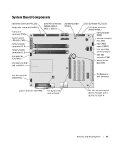
System Board Components hard-drive connector (PRI_IDE) floppy-drive connector (FLOPPY) main power connector (PWR) auxiliary power LED (AUX_PWR) memory module connectors (2, 4) memory module connectors (1, 3) processor fan (CPU FAN) processor and heatsink connector serial ATA connectors (SATA-0, SATA-1, SATA-2, SATA-3) password jumper (PASS) SCSI LED header (SCSI LED) ...
System Board Components hard-drive connector (PRI_IDE) floppy-drive connector (FLOPPY) main power connector (PWR) auxiliary power LED (AUX_PWR) memory module connectors (2, 4) memory module connectors (1, 3) processor fan (CPU FAN) processor and heatsink connector serial ATA connectors (SATA-0, SATA-1, SATA-2, SATA-3) password jumper (PASS) SCSI LED header (SCSI LED) ...
Owner's Manual
Page 76
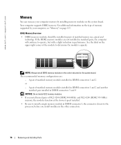
... connectors. 76 Removing and Installing Parts NOTE: Always install DDR2 memory modules in DIMM connectors 1 and 2 or - www.dell.com | support.dell.com Memory You can increase your computer, see "Memory" on page 115. For additional information on the type of memory supported by your computer memory by installing memory modules on the upper-right corner of matched...
... connectors. 76 Removing and Installing Parts NOTE: Always install DDR2 memory modules in DIMM connectors 1 and 2 or - www.dell.com | support.dell.com Memory You can increase your computer, see "Memory" on page 115. For additional information on the type of memory supported by your computer memory by installing memory modules on the upper-right corner of matched...
Owner's Manual
Page 77
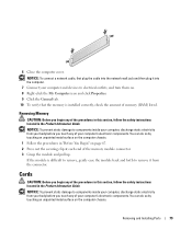
...) NOTE: Memory purchased from Dell. Removing and Installing Parts 77 Installing Memory CAUTION: Before you use four 1-GB DIMMs. Current operating systems, such as Microsoft® Windows® XP, can do not pair an original memory module with a new memory module. Otherwise, your original memory modules in ... electricity from your body before you purchased the new modules from Dell is less than 4 GB. If possible, do so by computer memory. You can only use a maximum of 4 GB of memory available to components inside of your computer's electronic components.
...) NOTE: Memory purchased from Dell. Removing and Installing Parts 77 Installing Memory CAUTION: Before you use four 1-GB DIMMs. Current operating systems, such as Microsoft® Windows® XP, can do not pair an original memory module with a new memory module. Otherwise, your original memory modules in ... electricity from your body before you purchased the new modules from Dell is less than 4 GB. If possible, do so by computer memory. You can only use a maximum of 4 GB of memory available to components inside of your computer's electronic components.

Owner's Manual
Page 78
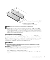
... cutouts (2) crossbar NOTICE: To avoid damage to the memory module, press the module straight down into the connector while you insert the module correctly, the securing clips snap into position. If you apply equal ...force to processor securing clips (2) connector 4 Align the notch on the bottom of the module with the crossbar in the connector. memory connector closest to each end of the module. 5 Insert the module into the connector until the module snaps into the cutouts at each end of...
... cutouts (2) crossbar NOTICE: To avoid damage to the memory module, press the module straight down into the connector while you insert the module correctly, the securing clips snap into position. If you apply equal ...force to processor securing clips (2) connector 4 Align the notch on the bottom of the module with the crossbar in the connector. memory connector closest to each end of the module. 5 Insert the module into the connector until the module snaps into the cutouts at each end of...
Owner's Manual
Page 79
... metal surface on . 8 Right-click the My Computer icon and click Properties. 9 Click the General tab. 10 To verify that the memory is installed correctly, check the amount of the procedures in this section, follow the safety instructions located in the Product Information Guide. NOTICE: ... any of your computer's electronic components. Removing and Installing Parts 79 6 Close the computer cover. Cards CAUTION: Before you touch any of memory (RAM) listed. If the module is difficult to remove, gently ease the module back and forth to electrical outlets, and turn them on...
... metal surface on . 8 Right-click the My Computer icon and click Properties. 9 Click the General tab. 10 To verify that the memory is installed correctly, check the amount of the procedures in this section, follow the safety instructions located in the Product Information Guide. NOTICE: ... any of your computer's electronic components. Removing and Installing Parts 79 6 Close the computer cover. Cards CAUTION: Before you touch any of memory (RAM) listed. If the module is difficult to remove, gently ease the module back and forth to electrical outlets, and turn them on...
Owner's Manual
Page 115
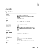
Appendix Specifications Processor Processor type Cache Memory Type Memory connectors Memory capacities Minimum memory Maximum memory BIOS address Computer Information Chipset DMA channels Interrupt levels BIOS chip (NVRAM) NIC System clock Video Type Intel® Pentium® 4 with HT Technology NOTE: ..., 1 MB, or 2 MB 400- and 533-MHz DDR2 unbuffered SDRAM four 256 MB, 512 MB, or 1 GB non-ECC 256 MB 4 GB NOTE: See "Addressing Memory With 4-GB Configurations" on your processor) PCI Express Appendix 115 or 1066-MHz data rate (depending on page 77 to the operating system. F0000h Intel...
Appendix Specifications Processor Processor type Cache Memory Type Memory connectors Memory capacities Minimum memory Maximum memory BIOS address Computer Information Chipset DMA channels Interrupt levels BIOS chip (NVRAM) NIC System clock Video Type Intel® Pentium® 4 with HT Technology NOTE: ..., 1 MB, or 2 MB 400- and 533-MHz DDR2 unbuffered SDRAM four 256 MB, 512 MB, or 1 GB non-ECC 256 MB 4 GB NOTE: See "Addressing Memory With 4-GB Configurations" on your processor) PCI Express Appendix 115 or 1066-MHz data rate (depending on page 77 to the operating system. F0000h Intel...
Owner's Manual
Page 116
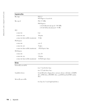
www.dell.com | support.dell.com Expansion Bus Bus type PCI 2.3 PCI Express x1 and x16 Bus speed PCI: 33 MHz PCI Express: x1 slot bidirectional speed - 500 MB/s x16 ...) 16 PCI Express lanes Drives Externally accessible: Available devices Internally accessible: two 3.5-inch drive bays two 5.25-inch drive bays Serial ATA drive, floppy drive, memory devices, CD drive, CD-RW drive, DVD drive, DVD-RW drive, and DVD and CD-RW combo drive two bays for 1-inch high hard drives...
www.dell.com | support.dell.com Expansion Bus Bus type PCI 2.3 PCI Express x1 and x16 Bus speed PCI: 33 MHz PCI Express: x1 slot bidirectional speed - 500 MB/s x16 ...) 16 PCI Express lanes Drives Externally accessible: Available devices Internally accessible: two 3.5-inch drive bays two 5.25-inch drive bays Serial ATA drive, floppy drive, memory devices, CD drive, CD-RW drive, DVD drive, DVD-RW drive, and DVD and CD-RW combo drive two bays for 1-inch high hard drives...

Owner's Manual
Page 119
... at 0.5 octave/min 0.5 G at 3 to 35,000 ft) System Setup Overview Use system setup as the user password • To read the current amount of memory or set the type of hard drive installed Before you use system setup, it is recommended that you write down the system setup screen information...
... at 0.5 octave/min 0.5 G at 3 to 35,000 ft) System Setup Overview Use system setup as the user password • To read the current amount of memory or set the type of hard drive installed Before you use system setup, it is recommended that you write down the system setup screen information...

Owner's Manual
Page 121
..., the computer attempts to the FLOPPY connector on the system board as Off, USB, Internal, or Read Only. Indicates amount of installed memory, memory speed, channel mode (dual or single), and type of devices specified in this option appears in the operating system. If a boot routine...information. System Setup Options NOTE: Depending on the system board, and lists the capacity for hard drives. To boot from the sequence of memory installed. Enables or disables the onboard PS/2-compatible mouse controller. Set to On (default), Off, or On w/ PXE. Identifies whether the ...
..., the computer attempts to the FLOPPY connector on the system board as Off, USB, Internal, or Read Only. Indicates amount of installed memory, memory speed, channel mode (dual or single), and type of devices specified in this option appears in the operating system. If a boot routine...information. System Setup Options NOTE: Depending on the system board, and lists the capacity for hard drives. To boot from the sequence of memory installed. Enables or disables the onboard PS/2-compatible mouse controller. Set to On (default), Off, or On w/ PXE. Identifies whether the ...

Owner's Manual
Page 123
... the start-up from Suspend. or left-arrow key to boot from suspend mode, hibernate mode, or when powered off for most components, however, system memory remains active. NOTE: Normally, the system can only be powered up signal. On is Off. On w/ Boot to NIC allows the computer to attempt to...
... the start-up from Suspend. or left-arrow key to boot from suspend mode, hibernate mode, or when powered off for most components, however, system memory remains active. NOTE: Normally, the system can only be powered up signal. On is Off. On w/ Boot to NIC allows the computer to attempt to...


