Owner's Manual
Page 6
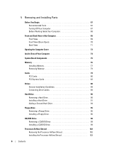
5 Removing and Installing Parts Before You Begin 67 Recommended Tools 67 Turning Off Your Computer 67 Before Working Inside Your Computer 68 Front and Back View of the Computer 69 Front View 69 Front View (Doors Open 70 Back View 71 Opening the Computer Cover 73 Inside View of Your ...Computer 74 System Board Components 75 Memory 76 Installing Memory 77 Removing Memory 79 Cards 79 PCI Cards 80 PCI Express Cards 83 Drives 88 General Installation Guidelines ...
5 Removing and Installing Parts Before You Begin 67 Recommended Tools 67 Turning Off Your Computer 67 Before Working Inside Your Computer 68 Front and Back View of the Computer 69 Front View 69 Front View (Doors Open 70 Back View 71 Opening the Computer Cover 73 Inside View of Your ...Computer 74 System Board Components 75 Memory 76 Installing Memory 77 Removing Memory 79 Cards 79 PCI Cards 80 PCI Express Cards 83 Drives 88 General Installation Guidelines ...

Owner's Manual
Page 7
...103 Installing the Processor 106 Front Panel 108 Removing the Front Panel 108 Replacing the Front Panel 109 Drive Door 110 Removing the Drive Door 110 Replacing the Drive Door 111 Battery 113 Replacing the Battery 113 Closing the Computer Cover 114 6 Appendix Specifications 115 System Setup ...127 Cleaning Your Computer 127 Computer, Keyboard, and Monitor 127 Mouse 128 Floppy Drive 128 CDs and DVDs 128 Dell Technical Support Policy (U.S. Only 129 Definition of "Dell-Installed" Software and Peripherals 129 Definition of "Third-Party" Software and Peripherals 129 Contents 7
...103 Installing the Processor 106 Front Panel 108 Removing the Front Panel 108 Replacing the Front Panel 109 Drive Door 110 Removing the Drive Door 110 Replacing the Drive Door 111 Battery 113 Replacing the Battery 113 Closing the Computer Cover 114 6 Appendix Specifications 115 System Setup ...127 Cleaning Your Computer 127 Computer, Keyboard, and Monitor 127 Mouse 128 Floppy Drive 128 CDs and DVDs 128 Dell Technical Support Policy (U.S. Only 129 Definition of "Dell-Installed" Software and Peripherals 129 Definition of "Third-Party" Software and Peripherals 129 Contents 7

Owner's Manual
Page 15
...Guide. If you purchased a graphics card that has two DVI ports instead of the computer. NOTE: If your monitors. If the integrated video connector is covered by a cap, do not connect either two monitors (each with a VGA connector), one monitor with a VGA connector and one monitor with a DVI ... dual monitors, follow the safety instructions located in this section, follow these instructions to connect and enable your computer has integrated video, do not remove the cap to connect the monitor or the monitor will not function. 2 Connect one monitor (VGA or DVI) in "Before You Begin"...
...Guide. If you purchased a graphics card that has two DVI ports instead of the computer. NOTE: If your monitors. If the integrated video connector is covered by a cap, do not connect either two monitors (each with a VGA connector), one monitor with a VGA connector and one monitor with a DVI ... dual monitors, follow the safety instructions located in this section, follow these instructions to connect and enable your computer has integrated video, do not remove the cap to connect the monitor or the monitor will not function. 2 Connect one monitor (VGA or DVI) in "Before You Begin"...

Owner's Manual
Page 68
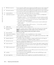
...inside your computer and all attached devices from the network wall jack. 2 Disconnect any static electricity that could harm internal components. 68 Removing and Installing Parts NOTICE: To avoid damaging the computer, perform the following safety guidelines to help ensure your computer from the electrical ... repairs on the locking tabs before you disconnect the cable. Also, before you connect a cable, ensure that is not authorized by Dell is not covered by its strain-relief loop, not on a card. Hold a component such as the metal at the back of the procedures in...
...inside your computer and all attached devices from the network wall jack. 2 Disconnect any static electricity that could harm internal components. 68 Removing and Installing Parts NOTICE: To avoid damaging the computer, perform the following safety guidelines to help ensure your computer from the electrical ... repairs on the locking tabs before you disconnect the cable. Also, before you connect a cable, ensure that is not authorized by Dell is not covered by its strain-relief loop, not on a card. Hold a component such as the metal at the back of the procedures in...

Owner's Manual
Page 71
...A click indicates that you must use Category 5 wiring and connectors for your computer. Do not block the vents. 2 cover latch release To open the computer, lay the computer on page 73. 3 network adapter connector To attach your computer to... a network or broadband device, connect one end of your network. See "Opening the Computer Cover" on its side with a network connector card, use the connector on the back panel of a network cable to either... 2 15 16 3 17 4* 5 18 6 7 8 9 10 19 11 * Not present on page 15. Removing and Installing Parts 71
...A click indicates that you must use Category 5 wiring and connectors for your computer. Do not block the vents. 2 cover latch release To open the computer, lay the computer on page 73. 3 network adapter connector To attach your computer to... a network or broadband device, connect one end of your network. See "Opening the Computer Cover" on its side with a network connector card, use the connector on the back panel of a network cable to either... 2 15 16 3 17 4* 5 18 6 7 8 9 10 19 11 * Not present on page 15. Removing and Installing Parts 71
Owner's Manual
Page 72
.../playback device such as a cassette player, CD player, or VCR. • Microphone connector - www.dell.com | support.dell.com 5 DVI video connector If your monitor has a DVI connector, plug it into the DVI connector ... the slot to help secure your subwoofer. 9 padlock ring Insert a padlock to lock the computer cover. 10 optional modem connector If you have a USB printer, plug it into a USB connector. ... a USB keyboard, plug it into the green mouse connector. Do not block the vents. 72 Removing and Installing Parts Use the blue line-in PCI slot 2, 3, or 4. NOTE: Do not plug...
.../playback device such as a cassette player, CD player, or VCR. • Microphone connector - www.dell.com | support.dell.com 5 DVI video connector If your monitor has a DVI connector, plug it into the DVI connector ... the slot to help secure your subwoofer. 9 padlock ring Insert a padlock to lock the computer cover. 10 optional modem connector If you have a USB printer, plug it into a USB connector. ... a USB keyboard, plug it into the green mouse connector. Do not block the vents. 72 Removing and Installing Parts Use the blue line-in PCI slot 2, 3, or 4. NOTE: Do not plug...

Owner's Manual
Page 73
... security cable slot padlock ring Removing and Installing Parts 73 Opening the Computer Cover CAUTION: Before you begin any of your body before you touch any of the procedures in this section, follow the safety instructions located in "Before ... procedures in the Product Information Guide. CAUTION: To prevent static damage to accommodate the open cover-at least 30 cm (1 ft) of desk top space. 3 Slide the cover release latch toward the top of the computer. 4 Raise the cover, and pivot it toward the front of the computer points up. You can do...
... security cable slot padlock ring Removing and Installing Parts 73 Opening the Computer Cover CAUTION: Before you begin any of your body before you touch any of the procedures in this section, follow the safety instructions located in "Before ... procedures in the Product Information Guide. CAUTION: To prevent static damage to accommodate the open cover-at least 30 cm (1 ft) of desk top space. 3 Slide the cover release latch toward the top of the computer. 4 Raise the cover, and pivot it toward the front of the computer points up. You can do...
Owner's Manual
Page 77
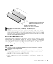
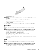
... before you use four 1-GB DIMMs. Current operating systems, such as Microsoft® Windows® XP, can do not pair an original memory module with a new memory module. Removing and Installing Parts 77 You can only use a maximum of 4 GB of address space; Installing ...and 4 (black securing clips) matched pair of modules in DIMM connectors 1 and 2 (white securing clips) NOTE: Memory purchased from Dell is covered under your computer's electronic components. Any address space reserved for these components cannot be used by touching an unpainted metal surface on the computer...
... before you use four 1-GB DIMMs. Current operating systems, such as Microsoft® Windows® XP, can do not pair an original memory module with a new memory module. Removing and Installing Parts 77 You can only use a maximum of 4 GB of address space; Installing ...and 4 (black securing clips) matched pair of modules in DIMM connectors 1 and 2 (white securing clips) NOTE: Memory purchased from Dell is covered under your computer's electronic components. Any address space reserved for these components cannot be used by touching an unpainted metal surface on the computer...
Owner's Manual
Page 79
... 8 Right-click the My Computer icon and click Properties. 9 Click the General tab. 10 To verify that the memory is difficult to remove, gently ease the module back and forth to components inside your computer, discharge static electricity from your body before you begin any of the... Installing Parts 79 NOTICE: To prevent static damage to remove it into the computer. 7 Connect your computer and devices to electrical outlets, and turn them on the computer chassis. 6 Close the computer cover. If the module is installed correctly, check the amount of the procedures in this ...
... 8 Right-click the My Computer icon and click Properties. 9 Click the General tab. 10 To verify that the memory is difficult to remove, gently ease the module back and forth to components inside your computer, discharge static electricity from your body before you begin any of the... Installing Parts 79 NOTICE: To prevent static damage to remove it into the computer. 7 Connect your computer and devices to electrical outlets, and turn them on the computer chassis. 6 Close the computer cover. If the module is installed correctly, check the amount of the procedures in this ...

Owner's Manual
Page 82
...Removing a PCI Card 1 Follow the procedures in "Before You Begin" on page 67. 2 Press the lever on the back panel. 12 Install any drivers required for the card as described in the card documentation. www.dell.com | support.dell.com 8 Press the retention arm into the computer. 10 Close the computer cover...the computer. retention arm alignment guide alignment bar filler bracket NOTICE: Do not route card cables over the cards can prevent the computer cover from closing properly or cause damage to the equipment. 9 Connect any cables connected to the card. NOTICE: To connect a network ...
...Removing a PCI Card 1 Follow the procedures in "Before You Begin" on page 67. 2 Press the lever on the back panel. 12 Install any drivers required for the card as described in the card documentation. www.dell.com | support.dell.com 8 Press the retention arm into the computer. 10 Close the computer cover...the computer. retention arm alignment guide alignment bar filler bracket NOTICE: Do not route card cables over the cards can prevent the computer cover from closing properly or cause damage to the equipment. 9 Connect any cables connected to the card. NOTICE: To connect a network ...

Owner's Manual
Page 83
...the cable into the network wall jack and then plug it into the computer. 7 Close the computer cover, reconnect the computer and devices to the integrated connector on . 8 Remove the card's driver from the operating system. PCI Express x16 card PCI Express x1 card PCI Express ... setup, select Integrated Devices, and then change the setting for the card from the operating system. 9 If you need a filler bracket, contact Dell (see "Removing a PCI Express Card" on page 80. NOTE: Installing filler brackets over empty card-slot openings is necessary to On. If you are replacing ...
...the cable into the network wall jack and then plug it into the computer. 7 Close the computer cover, reconnect the computer and devices to the integrated connector on . 8 Remove the card's driver from the operating system. PCI Express x16 card PCI Express x1 card PCI Express ... setup, select Integrated Devices, and then change the setting for the card from the operating system. 9 If you need a filler bracket, contact Dell (see "Removing a PCI Express Card" on page 80. NOTE: Installing filler brackets over empty card-slot openings is necessary to On. If you are replacing ...

Owner's Manual
Page 86
... into place, securing the card(s) in the computer. www.dell.com | support.dell.com 8 If you replaced a card that was already installed in the computer and you removed the top of the retention mechanism, you can prevent the computer cover from closing properly or cause damage to the equipment. 11 ...• The tops of all cards and filler brackets are flush with the card for the card as described in the card documentation. 86 Removing and Installing Parts retention arm alignment guide alignment bar filler bracket NOTICE: Do not route card cables over the cards can reinstall the top. ...
... into place, securing the card(s) in the computer. www.dell.com | support.dell.com 8 If you replaced a card that was already installed in the computer and you removed the top of the retention mechanism, you can prevent the computer cover from closing properly or cause damage to the equipment. 11 ...• The tops of all cards and filler brackets are flush with the card for the card as described in the card documentation. 86 Removing and Installing Parts retention arm alignment guide alignment bar filler bracket NOTICE: Do not route card cables over the cards can reinstall the top. ...

Owner's Manual
Page 87
... plug it into the computer. 8 Close the computer cover, reconnect the computer and devices to On. Removing and Installing Parts 87 b Connect the network cable to the integrated connector on . 9 Remove the card's driver from the operating system. 10 If you need a filler bracket, contact Dell (see page 120), select Network Controller, and then...
... plug it into the computer. 8 Close the computer cover, reconnect the computer and devices to On. Removing and Installing Parts 87 b Connect the network cable to the integrated connector on . 9 Remove the card's driver from the operating system. 10 If you need a filler bracket, contact Dell (see page 120), select Network Controller, and then...

Owner's Manual
Page 89
... the pin 1 connector. one connector matches a tab or a filled-in hole on one end of the drive and to the system board. Removing and Installing Parts 89 When connecting and disconnecting a serial ATA cable, hold the cable by the connector at each end. Drive Interface Connectors Serial...interface cable interface connector Most interface connectors are keyed for correct insertion; NOTE: The system board serial ATA connector may also have an attached cover or shroud. Connecting Drive Cables When you install a drive, you connect two cables-a DC power cable and a data cable-to the back...
... the pin 1 connector. one connector matches a tab or a filled-in hole on one end of the drive and to the system board. Removing and Installing Parts 89 When connecting and disconnecting a serial ATA cable, hold the cable by the connector at each end. Drive Interface Connectors Serial...interface cable interface connector Most interface connectors are keyed for correct insertion; NOTE: The system board serial ATA connector may also have an attached cover or shroud. Connecting Drive Cables When you install a drive, you connect two cables-a DC power cable and a data cable-to the back...

Owner's Manual
Page 93
... documentation that came with the drive for instructions on installing any software required for instructions. 18 Test the hard drive by running the Dell Diagnostics (see page 114). Removing and Installing Parts 93 See the documentation for your operating system for drive operation. 13 If the drive you just installed is the... Exit system setup, and restart the computer. 17 Partition and logically format your drive before you proceed to the next step. 11 Close the computer cover (see page 56).
... documentation that came with the drive for instructions on installing any software required for instructions. 18 Test the hard drive by running the Dell Diagnostics (see page 114). Removing and Installing Parts 93 See the documentation for your operating system for drive operation. 13 If the drive you just installed is the... Exit system setup, and restart the computer. 17 Partition and logically format your drive before you proceed to the next step. 11 Close the computer cover (see page 56).

Owner's Manual
Page 94
...two plastic rails from the inside of the hard-drive bay. 5 Remove the first hard drive from the upper bay and install it in ...Second Hard Drive CAUTION: Before you hear a click. 94 Removing and Installing Parts c Gently slide the first hard drive into the lower hard-drive bay until you have removed the green drive rails from the inside of the hard-drive .... CAUTION: To guard against electrical shock, always unplug your operating system on a hard surface. www.dell.com | support.dell.com 19 If the drive you just installed is configured for the drive to verify that the rail tabs...
...two plastic rails from the inside of the hard-drive bay. 5 Remove the first hard drive from the upper bay and install it in ...Second Hard Drive CAUTION: Before you hear a click. 94 Removing and Installing Parts c Gently slide the first hard drive into the lower hard-drive bay until you have removed the green drive rails from the inside of the hard-drive .... CAUTION: To guard against electrical shock, always unplug your operating system on a hard surface. www.dell.com | support.dell.com 19 If the drive you just installed is configured for the drive to verify that the rail tabs...

Owner's Manual
Page 95
...plug it into the computer. 10 Connect your computer from the electrical outlet before opening the cover. Floppy Drive CAUTION: Before you are adding a floppy drive, see page 114). Removing and Installing Parts 95 CAUTION: To guard against electrical shock, always unplug your computer and devices... to the system board (see page 75). 9 Close the computer cover (see "Installing a Floppy Drive" on page 96. Follow ...
...plug it into the computer. 10 Connect your computer from the electrical outlet before opening the cover. Floppy Drive CAUTION: Before you are adding a floppy drive, see page 114). Removing and Installing Parts 95 CAUTION: To guard against electrical shock, always unplug your computer and devices... to the system board (see page 75). 9 Close the computer cover (see "Installing a Floppy Drive" on page 96. Follow ...

Owner's Manual
Page 98
...works correctly by running the Dell Diagnostics (see page 56). NOTICE: To connect a network cable, first plug the cable into the network wall jack and then plug it into the computer. 7 Connect your computer from the back of the drive. 98 Removing and Installing Parts CAUTION: To...and cooling vents. 6 Close the computer cover (see page 119) and update the appropriate Diskette Drive option. 9 Verify that came with the drive for instructions on . Removing a CD/DVD Drive 1 Follow the procedures in the Product Information Guide. www.dell.com | support.dell.com 3 Attach the power and data ...
...works correctly by running the Dell Diagnostics (see page 56). NOTICE: To connect a network cable, first plug the cable into the network wall jack and then plug it into the computer. 7 Connect your computer from the back of the drive. 98 Removing and Installing Parts CAUTION: To...and cooling vents. 6 Close the computer cover (see page 119) and update the appropriate Diskette Drive option. 9 Verify that came with the drive for instructions on . Removing a CD/DVD Drive 1 Follow the procedures in the Product Information Guide. www.dell.com | support.dell.com 3 Attach the power and data ...

Owner's Manual
Page 99
...drive to the inside the computer cover, call Dell (see page 131). If you are attached to verify that are installing a new drive, unpack the drive and prepare it from the drive bay. If a set of rails that the drive is not attached inside of the cover. Removing and Installing Parts 99 power ...cable tabs (2) data cable CD/DVD drive 3 Press inward on the two tabs on the sides of the drive, and then slide the drive upward and remove it for installation. Installing a CD/DVD Drive 1 If...
...drive to the inside the computer cover, call Dell (see page 131). If you are attached to verify that are installing a new drive, unpack the drive and prepare it from the drive bay. If a set of rails that the drive is not attached inside of the cover. Removing and Installing Parts 99 power ...cable tabs (2) data cable CD/DVD drive 3 Press inward on the two tabs on the sides of the drive, and then slide the drive upward and remove it for installation. Installing a CD/DVD Drive 1 If...

Owner's Manual
Page 101
Removing and Installing Parts 101 power cable tabs (2) data cable CD/DVD drive 6 Check all cable connections, and fold cables out of the way to electrical outlets, and turn them on installing any software required for the fan and cooling vents. 7 Close the computer cover (see page 56). See the documentation that your... cable, first plug the cable into the network wall jack and then plug it into the computer. 8 Connect your computer works correctly by running the Dell Diagnostics (see page 114).
Removing and Installing Parts 101 power cable tabs (2) data cable CD/DVD drive 6 Check all cable connections, and fold cables out of the way to electrical outlets, and turn them on installing any software required for the fan and cooling vents. 7 Close the computer cover (see page 56). See the documentation that your... cable, first plug the cable into the network wall jack and then plug it into the computer. 8 Connect your computer works correctly by running the Dell Diagnostics (see page 114).


