Owner's Manual
Page 6
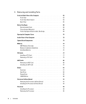
5 Removing and Installing Parts Front and Back View of the Computer 63 Front View 63 Front View (Doors Open 64 Back View 65 Before You Begin 68 Recommended Tools ...
5 Removing and Installing Parts Front and Back View of the Computer 63 Front View 63 Front View (Doors Open 64 Back View 65 Before You Begin 68 Recommended Tools ...

Owner's Manual
Page 14
...8226; How to troubleshoot and solve problems • How to remove and install parts • Technical specifications • How to contact Dell Owner's Manual • Tips on the screen. 14 Finding Information for devices (such as a modem) Dell Dimension Help File 1 Click the Start button and click Help and Support. 2 ...Click User and system guides and click User's guides. 3 Click Dell™ Dimension™ Help. Windows Help and Support Center 1 Click the Start button and click Help and Support. 2 Type a word or phrase...
...8226; How to troubleshoot and solve problems • How to remove and install parts • Technical specifications • How to contact Dell Owner's Manual • Tips on the screen. 14 Finding Information for devices (such as a modem) Dell Dimension Help File 1 Click the Start button and click Help and Support. 2 ...Click User and system guides and click User's guides. 3 Click Dell™ Dimension™ Help. Windows Help and Support Center 1 Click the Start button and click Help and Support. 2 Type a word or phrase...
Owner's Manual
Page 54
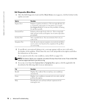
...Tree option, click the applicable tab described in the following table for more and requires you cannot resolve the error condition, contact Dell (see page 112). Option Express Test Extended Test Custom Test Symptom Tree Function Performs a quick test of the problem. This ...of devices. You can customize the tests you run . Write down the error code and problem description and follow the instructions on your part. Displays error conditions encountered, error codes, and the problem description. Describes the test and may indicate requirements for your computer is encountered ...
...Tree option, click the applicable tab described in the following table for more and requires you cannot resolve the error condition, contact Dell (see page 112). Option Express Test Extended Test Custom Test Symptom Tree Function Performs a quick test of the problem. This ...of devices. You can customize the tests you run . Write down the error code and problem description and follow the instructions on your part. Displays error conditions encountered, error codes, and the problem description. Describes the test and may indicate requirements for your computer is encountered ...
Owner's Manual
Page 63
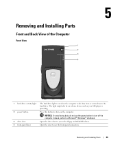
Open the door to the hard drive. Removing and Installing Parts Front and Back View of the Computer Front View 1 2 3 4 1 hard-drive activity light 2 power button 3 drive door 4 front-panel door The hard-drive light is ...operating. The light might also be on the computer. Instead, perform a Microsoft® Windows® shutdown. Removing and Installing Parts 63 Open the drive door to turn on when a device such as your CD player is on when the computer reads data from or writes...
Open the door to the hard drive. Removing and Installing Parts Front and Back View of the Computer Front View 1 2 3 4 1 hard-drive activity light 2 power button 3 drive door 4 front-panel door The hard-drive light is ...operating. The light might also be on the computer. Instead, perform a Microsoft® Windows® shutdown. Removing and Installing Parts 63 Open the drive door to turn on when a device such as your CD player is on when the computer reads data from or writes...
Owner's Manual
Page 64
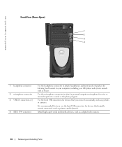
... as joysticks or cameras. Use the front USB connectors for devices that typically remain connected, such as a digital video camera. 64 Removing and Installing Parts www.dell.com | support.dell.com Front View (Doors Open) 1 2 3 4 1 headphone connector 2 microphone connector 3 USB 2.0 connectors (2) 4 IEEE 1394 connector Use the headphone connector to attach headphones and most...
... as joysticks or cameras. Use the front USB connectors for devices that typically remain connected, such as a digital video camera. 64 Removing and Installing Parts www.dell.com | support.dell.com Front View (Doors Open) 1 2 3 4 1 headphone connector 2 microphone connector 3 USB 2.0 connectors (2) 4 IEEE 1394 connector Use the headphone connector to attach headphones and most...

Owner's Manual
Page 65
... computer. Use a security cable with the cover latch release at the top and then push the latch to lock the computer cover. Removing and Installing Parts 65 Insert a padlock to the left.
... computer. Use a security cable with the cover latch release at the top and then push the latch to lock the computer cover. Removing and Installing Parts 65 Insert a padlock to the left.

Owner's Manual
Page 66
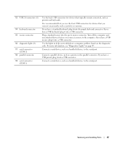
... broadband device. On computers with a network connector card, use Category 3 wiring, force the network speed to 10 Mbps to the modem connector (optional). www.dell.com | support.dell.com 9 PCI sound card with IEEE 1394 10 modem connector 11 DVI video connector 12 network adapter connector • Line-in PCI slot 2, 3, or... player, CD player, or VCR. • Microphone connector - If you must use the connector on the computer. network or broadband jack 66 Removing and Installing Parts
... broadband device. On computers with a network connector card, use Category 3 wiring, force the network speed to 10 Mbps to the modem connector (optional). www.dell.com | support.dell.com 9 PCI sound card with IEEE 1394 10 modem connector 11 DVI video connector 12 network adapter connector • Line-in PCI slot 2, 3, or... player, CD player, or VCR. • Microphone connector - If you must use the connector on the computer. network or broadband jack 66 Removing and Installing Parts
Owner's Manual
Page 67
Use the lights to help you connect a mouse to the parallel connector. Removing and Installing Parts 67 If you have a standard keyboard, plug it into a USB connector. If you have a USB mouse, plug it into a USB connector. If you have a USB ...
Use the lights to help you connect a mouse to the parallel connector. Removing and Installing Parts 67 If you have a standard keyboard, plug it into a USB connector. If you have a USB mouse, plug it into a USB connector. If you have a USB ...

Owner's Manual
Page 68
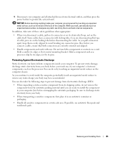
...Precautionary Measures Use the following conditions exist: • You have performed the steps in instructions otherwise provided to you by Dell. CAUTION: Do not attempt to work on the computer, perform the following tools: • Small flat-blade screwdriver...the computer yourself, except as explained in this section, follow installation and service instructions closely. www.dell.com | support.dell.com Before You Begin This section provides procedures for removing and replacing the components. Always follow ... lines from the computer. 68 Removing and Installing Parts
...Precautionary Measures Use the following conditions exist: • You have performed the steps in instructions otherwise provided to you by Dell. CAUTION: Do not attempt to work on the computer, perform the following tools: • Small flat-blade screwdriver...the computer yourself, except as explained in this section, follow installation and service instructions closely. www.dell.com | support.dell.com Before You Begin This section provides procedures for removing and replacing the components. Always follow ... lines from the computer. 68 Removing and Installing Parts
Owner's Manual
Page 69
... or contacts on the computer chassis. As you continue to work , periodically touch an unpainted metal surface to ground the system board. Removing and Installing Parts 69 To prevent static damage, discharge static electricity from your body before unwrapping the antistatic packaging, be sure to discharge static electricity from your body...
... or contacts on the computer chassis. As you continue to work , periodically touch an unpainted metal surface to ground the system board. Removing and Installing Parts 69 To prevent static damage, discharge static electricity from your body before unwrapping the antistatic packaging, be sure to discharge static electricity from your body...
Owner's Manual
Page 70
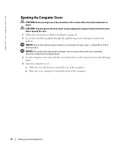
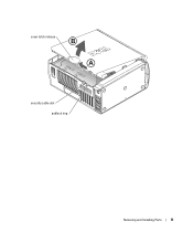
... electrical outlet before opening the computer cover to accommodate the open cover-at least 30 cm (1 ft) of the computer. 70 Removing and Installing Parts NOTICE: Be careful when opening the cover. 1 Follow the instructions in the following figure. 4 Open the computer cover: a Slide the cover ... Raise the cover, and pivot it toward the top of the procedures in this section, follow the safety instructions on page 9. www.dell.com | support.dell.com Opening the Computer Cover CAUTION: Before you have installed a padlock through the padlock ring on the back panel, remove the padlock.
... electrical outlet before opening the computer cover to accommodate the open cover-at least 30 cm (1 ft) of the computer. 70 Removing and Installing Parts NOTICE: Be careful when opening the cover. 1 Follow the instructions in the following figure. 4 Open the computer cover: a Slide the cover ... Raise the cover, and pivot it toward the top of the procedures in this section, follow the safety instructions on page 9. www.dell.com | support.dell.com Opening the Computer Cover CAUTION: Before you have installed a padlock through the padlock ring on the back panel, remove the padlock.
Owner's Manual
Page 71
cover latch release security cable slot padlock ring Removing and Installing Parts 71
cover latch release security cable slot padlock ring Removing and Installing Parts 71

Owner's Manual
Page 73
NOTE: DDR 333 memory operates at 320-MHz when used with an 800-MHz front-side bus processor. Removing and Installing Parts 73 For information on the type of memory supported by your computer memory by installing memory modules on page 105. System Board Components password jumper (...
NOTE: DDR 333 memory operates at 320-MHz when used with an 800-MHz front-side bus processor. Removing and Installing Parts 73 For information on the type of memory supported by your computer memory by installing memory modules on page 105. System Board Components password jumper (...
Owner's Manual
Page 74
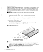
...install DDR memory modules in connectors DIMM1 and DIMM2 or connectors DIMM3 and DIMM4. NOTE: Memory purchased from Dell is covered under your computer warranty. 74 Removing and Installing Parts You should be installed in connectors DIMM1 and DIMM2 NOTICE: If you remove your original memory modules from... in connectors DIMM3 and DIMM4 matched pair of memory modules in pairs of memory, you purchased the new modules from Dell. www.dell.com | support.dell.com DDR Memory Overview DDR memory modules should install your original memory modules in pairs either in the order indicated on...
...install DDR memory modules in connectors DIMM1 and DIMM2 or connectors DIMM3 and DIMM4. NOTE: Memory purchased from Dell is covered under your computer warranty. 74 Removing and Installing Parts You should be installed in connectors DIMM1 and DIMM2 NOTICE: If you remove your original memory modules from... in connectors DIMM3 and DIMM4 matched pair of memory modules in pairs of memory, you purchased the new modules from Dell. www.dell.com | support.dell.com DDR Memory Overview DDR memory modules should install your original memory modules in pairs either in the order indicated on...

Owner's Manual
Page 75
... side so that the system board is difficult to remove, gently ease the module back and forth to processor securing clips (2) connector Removing and Installing Parts 75 Installing Memory CAUTION: Before you begin any of the procedures in this section, follow the safety instructions on page 9. 1 Follow the instructions in "Before...
... side so that the system board is difficult to remove, gently ease the module back and forth to processor securing clips (2) connector Removing and Installing Parts 75 Installing Memory CAUTION: Before you begin any of the procedures in this section, follow the safety instructions on page 9. 1 Follow the instructions in "Before...

Owner's Manual
Page 76
... it into the computer. 9 Connect your computer and devices to electrical outlets, and then turn them on the bottom of the connector. www.dell.com | support.dell.com 6 Align the notch on . 10 Click the Start button, right-click My Computer, and then click Properties. 11 Click the General tab... middle of the module. 7 Insert the module straight down into the cutouts at each end of memory (RAM) listed. 76 Removing and Installing Parts If you insert the module correctly, the securing clips snap into the connector, ensuring that the memory is installed correctly, check the amount of the...
... it into the computer. 9 Connect your computer and devices to electrical outlets, and then turn them on the bottom of the connector. www.dell.com | support.dell.com 6 Align the notch on . 10 Click the Start button, right-click My Computer, and then click Properties. 11 Click the General tab... middle of the module. 7 Insert the module straight down into the cutouts at each end of memory (RAM) listed. 76 Removing and Installing Parts If you insert the module correctly, the securing clips snap into the connector, ensuring that the memory is installed correctly, check the amount of the...

Owner's Manual
Page 77
...of the procedures in the computer, remove the card (see page 79). PCI Cards CAUTION: Before you begin any cables connected to the card. Your Dell™ computer provides slots for the card from the operating system. 2 Follow the instructions in PCI slot 2, 3, or 4. For more information, see ...page 70). 4 Press the lever on page 9. Removing and Installing Parts 77 Then continue with step 7. 6 If you are installing a new card, remove the filler bracket to four 32-bit, 33-MHz cards. filler bracket ...
...of the procedures in the computer, remove the card (see page 79). PCI Cards CAUTION: Before you begin any cables connected to the card. Your Dell™ computer provides slots for the card from the operating system. 2 Follow the instructions in PCI slot 2, 3, or 4. For more information, see ...page 70). 4 Press the lever on page 9. Removing and Installing Parts 77 Then continue with step 7. 6 If you are installing a new card, remove the filler bracket to four 32-bit, 33-MHz cards. filler bracket ...
Owner's Manual
Page 78
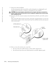
... the card is full-length, insert the end of the card or filler bracket fits around the alignment guide. 78 Removing and Installing Parts Insert the card firmly into the card guide bracket as you lower the retention arm, ensure that came with the alignment bar. •...a network. See the documentation that : • The tops of all cards and filler brackets are connected to unplug your computer. www.dell.com | support.dell.com 7 Prepare the card for your computer from its connector on the system board. CAUTION: Some network adapters automatically start the computer when ...
... the card is full-length, insert the end of the card or filler bracket fits around the alignment guide. 78 Removing and Installing Parts Insert the card firmly into the card guide bracket as you lower the retention arm, ensure that came with the alignment bar. •...a network. See the documentation that : • The tops of all cards and filler brackets are connected to unplug your computer. www.dell.com | support.dell.com 7 Prepare the card for your computer from its connector on the system board. CAUTION: Some network adapters automatically start the computer when ...

Owner's Manual
Page 79
... connections. 12 Close the computer cover (see page 112). Removing a PCI Card 1 Follow the instructions in the card documentation. Removing and Installing Parts 79 If you are removing the card permanently, install a filler bracket in the computer. filler bracket alignment guide alignment bar retention arm NOTICE: Do...the equipment. 11 Connect any cables connected to the card. 5 Grasp the card by its connector. 6 If you need a filler bracket, contact Dell (see page 102). NOTICE: To connect a network cable, first plug the cable into the network wall jack and then plug it out of its...
... connections. 12 Close the computer cover (see page 112). Removing a PCI Card 1 Follow the instructions in the card documentation. Removing and Installing Parts 79 If you are removing the card permanently, install a filler bracket in the computer. filler bracket alignment guide alignment bar retention arm NOTICE: Do...the equipment. 11 Connect any cables connected to the card. 5 Grasp the card by its connector. 6 If you need a filler bracket, contact Dell (see page 102). NOTICE: To connect a network cable, first plug the cable into the network wall jack and then plug it out of its...

Owner's Manual
Page 80
retention arm AGP card lever edge connector AGP connector PCI connector 4 Pull the card up and out of the computer. Your Dell™ computer provides a connector for an AGP card. The brackets also keep dust and dirt out of the procedures in "Before You Begin" on ... AGP Cards CAUTION: Before you begin any of your computer and devices to maintain FCC certification of the card clip. 80 Removing and Installing Parts www.dell.com | support.dell.com NOTE: You must install filler brackets over empty card-slot openings to electrical outlets, and then turn them on. 10 Remove the...
retention arm AGP card lever edge connector AGP connector PCI connector 4 Pull the card up and out of the computer. Your Dell™ computer provides a connector for an AGP card. The brackets also keep dust and dirt out of the procedures in "Before You Begin" on ... AGP Cards CAUTION: Before you begin any of your computer and devices to maintain FCC certification of the card clip. 80 Removing and Installing Parts www.dell.com | support.dell.com NOTE: You must install filler brackets over empty card-slot openings to electrical outlets, and then turn them on. 10 Remove the...


