Setup and Features Information Tech Sheet
Page 4
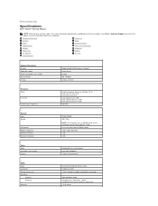
...) 3.34 A (continuous) 19.5 +/- 1.0 VDC 16 mm (0.63 inches) 66 mm (2.60 inches) 127 mm (5.00 inches) System Information Processor type Chipset Memory Memory module connector Memory module capacity Memory type Minimum memory Maximum memory Video Video type Video controller Battery Type Dimensions Depth Intel® Core™2 Solo Ultra Low Voltage (ULV), Intel Core2 Duo ULV...
...) 3.34 A (continuous) 19.5 +/- 1.0 VDC 16 mm (0.63 inches) 66 mm (2.60 inches) 127 mm (5.00 inches) System Information Processor type Chipset Memory Memory module connector Memory module capacity Memory type Minimum memory Maximum memory Video Video type Video controller Battery Type Dimensions Depth Intel® Core™2 Solo Ultra Low Voltage (ULV), Intel Core2 Duo ULV...
Service Manual
Page 2
...System Setup, it to your current settings. In this F2 prompt appears, press immediately. Back to Contents Page System Setup Dell™ Vostro™ V13 Service Manual Overview Entering System Setup System Setup Screens System Setup Options Overview Use System Setup as the user password l ...To read the current amount of memory or set or change a user-selectable option such as follows: l To change the system configuration ...
...System Setup, it to your current settings. In this F2 prompt appears, press immediately. Back to Contents Page System Setup Dell™ Vostro™ V13 Service Manual Overview Entering System Setup System Setup Screens System Setup Options Overview Use System Setup as the user password l ...To read the current amount of memory or set or change a user-selectable option such as follows: l To change the system configuration ...
Service Manual
Page 3
...Resets the time on . Displays the type of the hard drive. Displays the processor cache size. Displays the size of processor. Displays the memory speed. board NIC Default: Enabled Enable or disable the wireless LAN module. Default: Enabled Enable or disable the legacy support for the USB controllers... System Time System Date Bios Version CPU Type CPU Speed CPU Cache Size CPU ID Product Name Fixed HDD HDD Size System Memory Extended Memory Memory speed AC Adapter Type Resets the time on - Boot-time Diagnostic Screen QuickBoot Mode Intel® SpeedStep™ Technology No-Execute Mode...
...Resets the time on . Displays the type of the hard drive. Displays the processor cache size. Displays the size of processor. Displays the memory speed. board NIC Default: Enabled Enable or disable the wireless LAN module. Default: Enabled Enable or disable the legacy support for the USB controllers... System Time System Date Bios Version CPU Type CPU Speed CPU Cache Size CPU ID Product Name Fixed HDD HDD Size System Memory Extended Memory Memory speed AC Adapter Type Resets the time on - Boot-time Diagnostic Screen QuickBoot Mode Intel® SpeedStep™ Technology No-Execute Mode...
Service Manual
Page 5
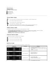
...-ON-FLASH display panel error 1. Turns on - Install compatible memory modules. Turns on when the numeric keypad is attached to indicate battery charge status. Replace the display panel. 3. Battery Status Lights If the computer is connected to Contents Page Diagnostics Dell™ Vostro™ V13 Service Manual Device Status Lights Battery Status Lights Keyboard...
...-ON-FLASH display panel error 1. Turns on - Install compatible memory modules. Turns on when the numeric keypad is attached to indicate battery charge status. Replace the display panel. 3. Battery Status Lights If the computer is connected to Contents Page Diagnostics Dell™ Vostro™ V13 Service Manual Device Status Lights Battery Status Lights Keyboard...
Service Manual
Page 6
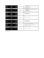
...two modules are installed remove one and test. Replace the system board. Test the computer with both modules. 3. Replace the system board. Reseat the memory. 2. Try the other module in the same slot and test. Test the other slot with just the hard drive and just the optical drive. 3.... board error 1. ON-FLASH-ON OFF-FLASH-FLASH FLASH-FLASH-FLASH FLASH-FLASH-OFF OFF-ON-OFF FLASH-FLASH-ON Back to Contents Page Memory compatibility error 2. Modem error 1. Try the other module in the same slot and test. If two modules are installed remove one and test...
...two modules are installed remove one and test. Replace the system board. Test the computer with both modules. 3. Replace the system board. Reseat the memory. 2. Try the other module in the same slot and test. Test the other slot with just the hard drive and just the optical drive. 3.... board error 1. ON-FLASH-ON OFF-FLASH-FLASH FLASH-FLASH-FLASH FLASH-FLASH-OFF OFF-ON-OFF FLASH-FLASH-ON Back to Contents Page Memory compatibility error 2. Modem error 1. Try the other module in the same slot and test. If two modules are installed remove one and test...
Service Manual
Page 7
Back to Contents Page Removing and Replacing Parts Dell™ Vostro™ V13 Service Manual ExpressCard Subscriber Identity Module (SIM) Card Base Cover Wireless Local Area Network (WLAN) Card Hard Drive and Audio Board Speaker Memory Coin-Cell Battery Heat Sink and Fan Assembly Display Panel Palm Rest and Display Assembly Hard Drive Cable Kit Secure Digital (SD) Card Battery SIM Card Reader Display Closure Sensor LED Cover Keyboard ExpressCard/SD Card Reader System Board Internal Card With Bluetooth® Wireless Technology Display Bezel Camera Back to Contents Page
Back to Contents Page Removing and Replacing Parts Dell™ Vostro™ V13 Service Manual ExpressCard Subscriber Identity Module (SIM) Card Base Cover Wireless Local Area Network (WLAN) Card Hard Drive and Audio Board Speaker Memory Coin-Cell Battery Heat Sink and Fan Assembly Display Panel Palm Rest and Display Assembly Hard Drive Cable Kit Secure Digital (SD) Card Battery SIM Card Reader Display Closure Sensor LED Cover Keyboard ExpressCard/SD Card Reader System Board Internal Card With Bluetooth® Wireless Technology Display Bezel Camera Back to Contents Page
Service Manual
Page 8
...width Flash EPROM PCI bus Processor Types L2 cache External bus frequency Memory Type Speed Connectors Module capacities Minimum memory Maximum memory Mobile Intel® GS45 Express Chipset 64-bit buses 36 bits SPI...-3 MB Intel Core2 Duo ULV-3 MB 800 MHz DDR3 SDRAM 1067 MHz NOTE: The memory runs at 800 MHz due to the limitations of your computer, click Start® Help...-accessible SODIMM socket 1 GB, 2 GB, and 4 GB 1 GB 4 GB Video Type Controller and memory Output Audio Type Controller Stereo conversion Interface: Internal External Speakers integrated on system board Intel GMA X4500HD 15-pin...
...width Flash EPROM PCI bus Processor Types L2 cache External bus frequency Memory Type Speed Connectors Module capacities Minimum memory Maximum memory Mobile Intel® GS45 Express Chipset 64-bit buses 36 bits SPI...-3 MB Intel Core2 Duo ULV-3 MB 800 MHz DDR3 SDRAM 1067 MHz NOTE: The memory runs at 800 MHz due to the limitations of your computer, click Start® Help...-accessible SODIMM socket 1 GB, 2 GB, and 4 GB 1 GB 4 GB Video Type Controller and memory Output Audio Type Controller Stereo conversion Interface: Internal External Speakers integrated on system board Intel GMA X4500HD 15-pin...
Service Manual
Page 9
...-Card microphone connector, stereo headphone/ speakers connector 15-pin VGA connector RJ-45 connector one 4-pin USB 2.0-compliant connector, one eSATA/USB 2.0-compliant connector 5-in-1 memory card reader PCI-E Half-Mini Card support for WLAN PCI-E Full-Mini Card support for WWAN Display Type Size Active area (X/Y) Dimensions: Height Width Diagonal...
...-Card microphone connector, stereo headphone/ speakers connector 15-pin VGA connector RJ-45 connector one 4-pin USB 2.0-compliant connector, one eSATA/USB 2.0-compliant connector 5-in-1 memory card reader PCI-E Half-Mini Card support for WLAN PCI-E Full-Mini Card support for WWAN Display Type Size Active area (X/Y) Dimensions: Height Width Diagonal...
Service Manual
Page 14
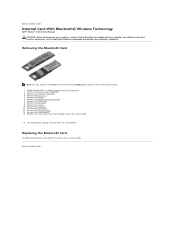
...the keyboard. 11. Remove the card reader. 12. Back to Contents Page Internal Card With Bluetooth® Wireless Technology Dell™ Vostro™ V13 Service Manual WARNING: Before working inside your computer. Remove the ExpressCard, if applicable. 3. Remove the base cover. ... Follow the procedures in reverse order. Remove the SD card, if applicable. 4. Remove the memory. 10. For additional safety best practices information, see the Regulatory Compliance Homepage at www.dell.com/regulatory_compliance. Remove the hard drive and audio board. 7. Remove the battery. 6. Remove ...
...the keyboard. 11. Remove the card reader. 12. Back to Contents Page Internal Card With Bluetooth® Wireless Technology Dell™ Vostro™ V13 Service Manual WARNING: Before working inside your computer. Remove the ExpressCard, if applicable. 3. Remove the base cover. ... Follow the procedures in reverse order. Remove the SD card, if applicable. 4. Remove the memory. 10. For additional safety best practices information, see the Regulatory Compliance Homepage at www.dell.com/regulatory_compliance. Remove the hard drive and audio board. 7. Remove the battery. 6. Remove ...
Service Manual
Page 17
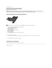
...-drive data cable to the computer. 12. For additional safety best practices information, see the Regulatory Compliance Homepage at www.dell.com/regulatory_compliance. Follow the procedures in reverse order. Remove the base cover. 5. Remove the screws that shipped with your ... Before Working Inside Your Computer. 2. Remove the WLAN card. 8. Remove the memory. 10. Remove the SD card, if applicable. 4. Back to Contents Page ExpressCard/SD Card Reader Dell™ Vostro™ V13 Service Manual WARNING: Before working inside your computer. Remove the LCD cover. 9....
...-drive data cable to the computer. 12. For additional safety best practices information, see the Regulatory Compliance Homepage at www.dell.com/regulatory_compliance. Follow the procedures in reverse order. Remove the base cover. 5. Remove the screws that shipped with your ... Before Working Inside Your Computer. 2. Remove the WLAN card. 8. Remove the memory. 10. Remove the SD card, if applicable. 4. Back to Contents Page ExpressCard/SD Card Reader Dell™ Vostro™ V13 Service Manual WARNING: Before working inside your computer. Remove the LCD cover. 9....
Service Manual
Page 25
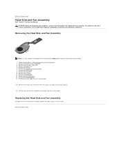
...additional safety best practices information, see the Regulatory Compliance Homepage at www.dell.com/regulatory_compliance. Disconnect the fan cable from the system board. Follow ..., if applicable. 3. Remove the base cover. 5. Remove the hard drive and audio board. 7. Remove the memory. 10. Replacing the Heat Sink and Fan Assembly To replace the heat sink and fan assembly, perform the above... order to Contents Page Heat Sink and Fan Assembly Dell™ Vostro™ V13 Service Manual WARNING: Before working inside your computer. Back to view the illustrations below. 1.
...additional safety best practices information, see the Regulatory Compliance Homepage at www.dell.com/regulatory_compliance. Disconnect the fan cable from the system board. Follow ..., if applicable. 3. Remove the base cover. 5. Remove the hard drive and audio board. 7. Remove the memory. 10. Replacing the Heat Sink and Fan Assembly To replace the heat sink and fan assembly, perform the above... order to Contents Page Heat Sink and Fan Assembly Dell™ Vostro™ V13 Service Manual WARNING: Before working inside your computer. Back to view the illustrations below. 1.
Service Manual
Page 29
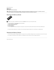
... from its connector on the system board, drawing the module from Adobe.com in order to view the illustrations below. 1. Back to Contents Page Memory Dell™ Vostro™ V13 Service Manual WARNING: Before working inside your computer, read the safety information that shipped with the tab on the connector. 2. Follow the procedures in...
... from its connector on the system board, drawing the module from Adobe.com in order to view the illustrations below. 1. Back to Contents Page Memory Dell™ Vostro™ V13 Service Manual WARNING: Before working inside your computer, read the safety information that shipped with the tab on the connector. 2. Follow the procedures in...
Service Manual
Page 30
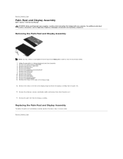
...board. 7. Back to release the display assembly from Adobe.com in order to Contents Page Palm Rest and Display Assembly Dell™ Vostro™ V13 Service Manual WARNING: Before working inside your computer, read the safety information that shipped with your computer. Removing the ...from the palm rest. 16. Remove the memory. 10. Remove the system board. 14. Remove the LCD cover. 9. Remove the coin-cell battery. 13. For additional safety best practices information, see the Regulatory Compliance Homepage at www.dell.com/regulatory_compliance. Back to view the illustrations below...
...board. 7. Back to release the display assembly from Adobe.com in order to Contents Page Palm Rest and Display Assembly Dell™ Vostro™ V13 Service Manual WARNING: Before working inside your computer, read the safety information that shipped with your computer. Removing the ...from the palm rest. 16. Remove the memory. 10. Remove the system board. 14. Remove the LCD cover. 9. Remove the coin-cell battery. 13. For additional safety best practices information, see the Regulatory Compliance Homepage at www.dell.com/regulatory_compliance. Back to view the illustrations below...
Service Manual
Page 37
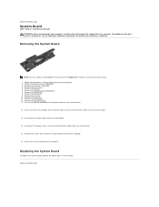
... the illustrations below. 1. For additional safety best practices information, see the Regulatory Compliance Homepage at www.dell.com/regulatory_compliance. Remove the LCD cover. 9. Remove the keyboard. 11. Back to Contents Page System Board Dell™ Vostro™ V13 Service Manual WARNING: Before working inside your computer. Remove the WLAN card. 8. Remove the system board... and fan to the computer. 18. Remove the base cover. 5. Disconnect the display status sensor and touch-pad flex cables from the computer. Remove the memory. 10. Remove the battery. 6.
... the illustrations below. 1. For additional safety best practices information, see the Regulatory Compliance Homepage at www.dell.com/regulatory_compliance. Remove the LCD cover. 9. Remove the keyboard. 11. Back to Contents Page System Board Dell™ Vostro™ V13 Service Manual WARNING: Before working inside your computer. Remove the WLAN card. 8. Remove the system board... and fan to the computer. 18. Remove the base cover. 5. Disconnect the display status sensor and touch-pad flex cables from the computer. Remove the memory. 10. Remove the battery. 6.


