Service Manual
Page 2
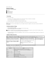
...item to display. Appears on (or restart) your current settings. Press to make changes to your computer l To set the type of hard drive installed Before you use System Setup, it to display, and then press . As a Menu option is highlighted, the Options Field displays the... the Options Field and lists keys and their functions within the active system setup field. Back to Contents Page System Setup Dell™ Vostro™ V13 Service Manual Overview Entering System Setup System Setup Screens System Setup Options Overview Use System Setup as the user password l To...
...item to display. Appears on (or restart) your current settings. Press to make changes to your computer l To set the type of hard drive installed Before you use System Setup, it to display, and then press . As a Menu option is highlighted, the Options Field displays the... the Options Field and lists keys and their functions within the active system setup field. Back to Contents Page System Setup Dell™ Vostro™ V13 Service Manual Overview Entering System Setup System Setup Screens System Setup Options Overview Use System Setup as the user password l To...
Service Manual
Page 3
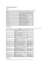
...Microphone Control Keyboard Click Advanced Enable or disable the system information from standby. Default: Enabled Allows the clock speed of the hard drive. board NIC Default: Enabled Enable or disable the wireless LAN module. Change the SATA controller mode to wake-up the ...the AC adapter is connected. Default: Enabled Allows increased protection against buffer overflow Default: Enabled attacks. Displays the type of the hard drive. System Setup Options Main The Main tab lists out the primary hardware features of each option. Display the BIOS revision. Default:...
...Microphone Control Keyboard Click Advanced Enable or disable the system information from standby. Default: Enabled Allows the clock speed of the hard drive. board NIC Default: Enabled Enable or disable the wireless LAN module. Change the SATA controller mode to wake-up the ...the AC adapter is connected. Default: Enabled Allows increased protection against buffer overflow Default: Enabled attacks. Displays the type of the hard drive. System Setup Options Main The Main tab lists out the primary hardware features of each option. Display the BIOS revision. Default:...
Service Manual
Page 4
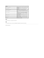
... Exit This section allows you to save, discard, and load default settings before exiting from System Setup. The hard drive password is enabled even when the hard drive is replaced. Displays the current service tag of the computer. Specifies whether a user password has been assigned.... Allows you to set a password on the computer's internal hard drive (HDD). Security Supervisor Password Is User Password Is Set Supervisor Password Set User Password Set HDD Password Password on another computer. ...
... Exit This section allows you to save, discard, and load default settings before exiting from System Setup. The hard drive password is enabled even when the hard drive is replaced. Displays the current service tag of the computer. Specifies whether a user password has been assigned.... Allows you to set a password on the computer's internal hard drive (HDD). Security Supervisor Password Is User Password Is Set Supervisor Password Set User Password Set HDD Password Password on another computer. ...
Service Manual
Page 6
... both modules. 3. Test the other module in the same slot and test. Memory is causing the failure. 4. Modem error 1. Reseat the hard drive and optical drive. 2. Video card error 1. ON-FLASH-ON OFF-FLASH-FLASH FLASH-FLASH-FLASH FLASH-FLASH-OFF OFF-ON-OFF FLASH-FLASH-ON Back to... Contents Page Memory compatibility error 2. Reseat the memory. 2. Try the other slot with just the hard drive and just the optical drive. 3. Test the other module in the same slot and test. Replace the memory. 4. Replace the modem. 3. Replace the system board...
... both modules. 3. Test the other module in the same slot and test. Memory is causing the failure. 4. Modem error 1. Reseat the hard drive and optical drive. 2. Video card error 1. ON-FLASH-ON OFF-FLASH-FLASH FLASH-FLASH-FLASH FLASH-FLASH-OFF OFF-ON-OFF FLASH-FLASH-ON Back to... Contents Page Memory compatibility error 2. Reseat the memory. 2. Try the other slot with just the hard drive and just the optical drive. 3. Test the other module in the same slot and test. Replace the memory. 4. Replace the modem. 3. Replace the system board...
Service Manual
Page 7
Back to Contents Page Removing and Replacing Parts Dell™ Vostro™ V13 Service Manual ExpressCard Subscriber Identity Module (SIM) Card Base Cover Wireless Local Area Network (WLAN) Card Hard Drive and Audio Board Speaker Memory Coin-Cell Battery Heat Sink and Fan Assembly Display Panel Palm Rest and Display Assembly Hard Drive Cable Kit Secure Digital (SD) Card Battery SIM Card Reader Display Closure Sensor LED Cover Keyboard ExpressCard/SD Card Reader System Board Internal Card With Bluetooth® Wireless Technology Display Bezel Camera Back to Contents Page
Back to Contents Page Removing and Replacing Parts Dell™ Vostro™ V13 Service Manual ExpressCard Subscriber Identity Module (SIM) Card Base Cover Wireless Local Area Network (WLAN) Card Hard Drive and Audio Board Speaker Memory Coin-Cell Battery Heat Sink and Fan Assembly Display Panel Palm Rest and Display Assembly Hard Drive Cable Kit Secure Digital (SD) Card Battery SIM Card Reader Display Closure Sensor LED Cover Keyboard ExpressCard/SD Card Reader System Board Internal Card With Bluetooth® Wireless Technology Display Bezel Camera Back to Contents Page

Service Manual
Page 11
Altitude: Operating Storage -15.2 m to 3048 m (-50 ft to 10,000 ft) -15.2 m to 10,668 m (-50 ft to 35,000 ft) Airborne contaminant level G2 or lower as defined by ANSI/ISA-S71.04-1985 Back to Contents Page NOTE: Shock is measured with hard drive in head-parked position and a 2-ms half-sine pulse.
Altitude: Operating Storage -15.2 m to 3048 m (-50 ft to 10,000 ft) -15.2 m to 10,668 m (-50 ft to 35,000 ft) Airborne contaminant level G2 or lower as defined by ANSI/ISA-S71.04-1985 Back to Contents Page NOTE: Shock is measured with hard drive in head-parked position and a 2-ms half-sine pulse.
Service Manual
Page 12
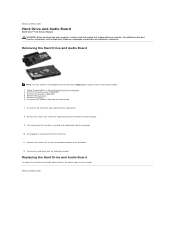
... the screws that shipped with your computer, read the safety information that secure the audio board and the hard drive to the computer. 9. Back to the hard drive. 12. Back to Contents Page Hard Drive and Audio Board Dell Vostro™ V13 Service Manual WARNING: Before working inside your computer. Remove the ExpressCard, if applicable. 3. Disconnect the speaker cable...
... the screws that shipped with your computer, read the safety information that secure the audio board and the hard drive to the computer. 9. Back to the hard drive. 12. Back to Contents Page Hard Drive and Audio Board Dell Vostro™ V13 Service Manual WARNING: Before working inside your computer. Remove the ExpressCard, if applicable. 3. Disconnect the speaker cable...
Service Manual
Page 14
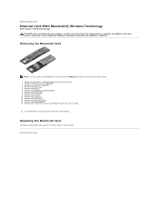
...applicable. 3. Remove the memory. 10. Follow the procedures in reverse order. Remove the hard drive and audio board. 7. For additional safety best practices information, see the Regulatory Compliance Homepage at www.dell.com/regulatory_compliance. Remove the SD card, if applicable. 4. Remove the coin-cell battery. ...com in order to the system board. 15. Back to Contents Page Internal Card With Bluetooth® Wireless Technology Dell™ Vostro™ V13 Service Manual WARNING: Before working inside your computer, read the safety information that secures the Bluetooth card to view the ...
...applicable. 3. Remove the memory. 10. Follow the procedures in reverse order. Remove the hard drive and audio board. 7. For additional safety best practices information, see the Regulatory Compliance Homepage at www.dell.com/regulatory_compliance. Remove the SD card, if applicable. 4. Remove the coin-cell battery. ...com in order to the system board. 15. Back to Contents Page Internal Card With Bluetooth® Wireless Technology Dell™ Vostro™ V13 Service Manual WARNING: Before working inside your computer, read the safety information that secures the Bluetooth card to view the ...
Service Manual
Page 17
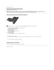
... the procedures in reverse order. Remove the keyboard. 11. Back to Contents Page ExpressCard/SD Card Reader Dell™ Vostro™ V13 Service Manual WARNING: Before working inside your computer. Lift the clip that secures the hard-drive data cable to the system board and disconnect it from Adobe.com in order to view the...
... the procedures in reverse order. Remove the keyboard. 11. Back to Contents Page ExpressCard/SD Card Reader Dell™ Vostro™ V13 Service Manual WARNING: Before working inside your computer. Lift the clip that secures the hard-drive data cable to the system board and disconnect it from Adobe.com in order to view the...
Service Manual
Page 18
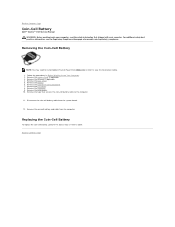
Remove the SD card, if applicable. 4. Remove the hard drive and audio board. 7. Replacing the Coin-Cell Battery To replace the coin-cell battery, perform the above steps in Before Working Inside Your Computer. 2. ...the system board. 12. For additional safety best practices information, see the Regulatory Compliance Homepage at www.dell.com/regulatory_compliance. Remove the base cover. 5. Back to Contents Page Coin-Cell Battery Dell™ Vostro™ V13 Service Manual WARNING: Before working inside your computer, read the safety information that secures the coin-cell ...
Remove the SD card, if applicable. 4. Remove the hard drive and audio board. 7. Replacing the Coin-Cell Battery To replace the coin-cell battery, perform the above steps in Before Working Inside Your Computer. 2. ...the system board. 12. For additional safety best practices information, see the Regulatory Compliance Homepage at www.dell.com/regulatory_compliance. Remove the base cover. 5. Back to Contents Page Coin-Cell Battery Dell™ Vostro™ V13 Service Manual WARNING: Before working inside your computer, read the safety information that secures the coin-cell ...
Service Manual
Page 21
... to view the illustrations below. 1. For additional safety best practices information, see the Regulatory Compliance Homepage at www.dell.com/regulatory_compliance. Follow the procedures in order to Contents Page Hard Drive Cable Kit Dell™ Vostro™ 13 Service Manual WARNING: Before working inside your computer, read the safety information that shipped with your computer...
... to view the illustrations below. 1. For additional safety best practices information, see the Regulatory Compliance Homepage at www.dell.com/regulatory_compliance. Follow the procedures in order to Contents Page Hard Drive Cable Kit Dell™ Vostro™ 13 Service Manual WARNING: Before working inside your computer, read the safety information that shipped with your computer...

Service Manual
Page 22
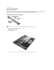
NOTE: Skip this step if the cloth tape is attached with a double sided tape. Remove the cloth tape from the system. 8. Peel off the cable from the card reader board edge. The hard drive flex cable is not present. 7.
NOTE: Skip this step if the cloth tape is attached with a double sided tape. Remove the cloth tape from the system. 8. Peel off the cable from the card reader board edge. The hard drive flex cable is not present. 7.

Service Manual
Page 23
Peel off the double sided tape from the hard drive flex cable. Peel off the double sided tape and attach the rubber bumper to the system board connector. Connect the cable end labeled 'HDD' to the hard drive connector first, follow by connecting the other end to the system. 10. 9.
Peel off the double sided tape from the hard drive flex cable. Peel off the double sided tape and attach the rubber bumper to the system board connector. Connect the cable end labeled 'HDD' to the hard drive connector first, follow by connecting the other end to the system. 10. 9.

Service Manual
Page 24
... information. This is to the flex cable. 11. Using the halo lines on the below picture as a guideline, do not add unnecessary pressure at the hard drive and card reader location. NOTE: When replacing the bottom base cover, do not press beyond the suggested line or to the edge of the card...
... information. This is to the flex cable. 11. Using the halo lines on the below picture as a guideline, do not add unnecessary pressure at the hard drive and card reader location. NOTE: When replacing the bottom base cover, do not press beyond the suggested line or to the edge of the card...
Service Manual
Page 25
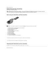
... below. 1. Remove the base cover. 5. For additional safety best practices information, see the Regulatory Compliance Homepage at www.dell.com/regulatory_compliance. Remove the hard drive and audio board. 7. Remove the keyboard. 11. Remove the system board. 14. Replacing the Heat Sink and Fan Assembly...the LCD cover. 9. Disconnect the fan cable from the system board. Back to Contents Page Heat Sink and Fan Assembly Dell™ Vostro™ V13 Service Manual WARNING: Before working inside your computer. Remove the coin-cell battery. 13. Lift the heat sink and fan...
... below. 1. Remove the base cover. 5. For additional safety best practices information, see the Regulatory Compliance Homepage at www.dell.com/regulatory_compliance. Remove the hard drive and audio board. 7. Remove the keyboard. 11. Remove the system board. 14. Replacing the Heat Sink and Fan Assembly...the LCD cover. 9. Disconnect the fan cable from the system board. Back to Contents Page Heat Sink and Fan Assembly Dell™ Vostro™ V13 Service Manual WARNING: Before working inside your computer. Remove the coin-cell battery. 13. Lift the heat sink and fan...
Service Manual
Page 30
... the hard drive and audio board. 7. Release the antennae, camera, and display cables and remove them from Adobe.com in order to release the display assembly from the display assembly. Remove the palm rest from the palm rest. 16. Back to Contents Page Palm Rest and Display Assembly Dell™ Vostro™ V13 Service...the left of the display hinge. 15. Remove the memory. 10. For additional safety best practices information, see the Regulatory Compliance Homepage at www.dell.com/regulatory_compliance. Follow the procedures in reverse order. Back to Contents Page
... the hard drive and audio board. 7. Release the antennae, camera, and display cables and remove them from Adobe.com in order to release the display assembly from the display assembly. Remove the palm rest from the palm rest. 16. Back to Contents Page Palm Rest and Display Assembly Dell™ Vostro™ V13 Service...the left of the display hinge. 15. Remove the memory. 10. For additional safety best practices information, see the Regulatory Compliance Homepage at www.dell.com/regulatory_compliance. Follow the procedures in reverse order. Back to Contents Page
Service Manual
Page 37
...below. 1. Replacing the System Board To replace the system board, perform the above steps in Before Working Inside Your Computer. 2. Remove the hard drive and audio board. 7. Remove the memory. 10. Remove the system board from the system board. 14. For additional safety best practices information..., read the safety information that secure the system board and fan to the computer. 18. Back to Contents Page System Board Dell™ Vostro™ V13 Service Manual WARNING: Before working inside your computer. Remove the base cover. 5. Gently turn over the computer and remove the ...
...below. 1. Replacing the System Board To replace the system board, perform the above steps in Before Working Inside Your Computer. 2. Remove the hard drive and audio board. 7. Remove the memory. 10. Remove the system board from the system board. 14. For additional safety best practices information..., read the safety information that secure the system board and fan to the computer. 18. Back to Contents Page System Board Dell™ Vostro™ V13 Service Manual WARNING: Before working inside your computer. Remove the base cover. 5. Gently turn over the computer and remove the ...
Service Manual
Page 39
... pull-tab, not on a flat work surface. Remove the main battery (see Hard Drive). Remove the hard drive (see Battery). 8. Shut down on the cable itself. Hold a card by its edges or by Dell is flat and clean to prevent the computer cover from being scratched. 2. Ensure... in this document may only be replaced or--if purchased separately--installed by your computer. 1. Working on Your Computer Dell™ Vostro™ V13 Service Manual Before Working Inside Your Computer Recommended Tools Turning Off Your Computer After Working Inside Your Computer Before Working Inside...
... pull-tab, not on a flat work surface. Remove the main battery (see Hard Drive). Remove the hard drive (see Battery). 8. Shut down on the cable itself. Hold a card by its edges or by Dell is flat and clean to prevent the computer cover from being scratched. 2. Ensure... in this document may only be replaced or--if purchased separately--installed by your computer. 1. Working on Your Computer Dell™ Vostro™ V13 Service Manual Before Working Inside Your Computer Recommended Tools Turning Off Your Computer After Working Inside Your Computer Before Working Inside...


