Handling swollen Lithium-ion batteries
Page 1
... power on when the power button is pressed, the battery is the potential for swelling of the battery cells Swollen battery may be replaced and disposed of Dell Inc. Contact Dell product support at an approved recycling center. Replace the battery only with a compatible battery purchased from Dell. 1 Swollen batteries should not be used and should be returned to...
... power on when the power button is pressed, the battery is the potential for swelling of the battery cells Swollen battery may be replaced and disposed of Dell Inc. Contact Dell product support at an approved recycling center. Replace the battery only with a compatible battery purchased from Dell. 1 Swollen batteries should not be used and should be returned to...

Handling swollen Lithium-ion batteries
Page 2
Frequently Asked Questions. 2 Lithium-ion batteries can swell for various reasons such as age, number of the issue, see Dell Laptop Battery - For more information on how to improve the performance and lifespan of the laptop battery and to minimize the possibility of occurrence of charge cycles, or exposure to high heat.
Frequently Asked Questions. 2 Lithium-ion batteries can swell for various reasons such as age, number of the issue, see Dell Laptop Battery - For more information on how to improve the performance and lifespan of the laptop battery and to minimize the possibility of occurrence of charge cycles, or exposure to high heat.
Ownerss Manual
Page 3
... computer...7 Safety instructions...7 Turning off your computer...8 2 Removing and installing components 9 Base cover...9 Removing the base cover...9 Installing the base cover...10 Battery...10 Removing the battery...10 Installing the battery...11 Speaker...12 Removing the speaker...12 Installing the speaker...13 Hard drive...13 Removing the hard drive...13 Installing the hard...
... computer...7 Safety instructions...7 Turning off your computer...8 2 Removing and installing components 9 Base cover...9 Removing the base cover...9 Installing the base cover...10 Battery...10 Removing the battery...10 Installing the battery...11 Speaker...12 Removing the speaker...12 Installing the speaker...13 Hard drive...13 Removing the hard drive...13 Installing the hard...
Ownerss Manual
Page 5
... specification...51 Ports and connectors specification...51 Display specification...51 Keyboard...52 Touchpad specification...52 Camera...52 Storage specification...52 Battery specification...52 AC adapter...53 Physical specification...53 Environmental specification...54 5 System setup...55 Boot menu...55 Navigation keys......in Windows ...65 Updating BIOS on systems with BitLocker enabled 66 Updating your system BIOS using a USB flash drive 66 Updating the Dell BIOS in Linux and Ubuntu environments 67 Flashing the BIOS from the F12 One-Time boot menu 67 System and setup password...70 ...
... specification...51 Ports and connectors specification...51 Display specification...51 Keyboard...52 Touchpad specification...52 Camera...52 Storage specification...52 Battery specification...52 AC adapter...53 Physical specification...53 Environmental specification...54 5 System setup...55 Boot menu...55 Navigation keys......in Windows ...65 Updating BIOS on systems with BitLocker enabled 66 Updating your system BIOS using a USB flash drive 66 Updating the Dell BIOS in Linux and Ubuntu environments 67 Flashing the BIOS from the F12 One-Time boot menu 67 System and setup password...70 ...
Ownerss Manual
Page 6
7 Troubleshooting...76 Dell Enhanced Pre-Boot System Assessment - ePSA Diagnostic 3.0 76 Running the ePSA Diagnostics...76 Diagnostic LED...76 Battery status lights...77 8 Contacting Dell...78 6 Contents
7 Troubleshooting...76 Dell Enhanced Pre-Boot System Assessment - ePSA Diagnostic 3.0 76 Running the ePSA Diagnostics...76 Diagnostic LED...76 Battery status lights...77 8 Contacting Dell...78 6 Contents
Ownerss Manual
Page 8
...if available). Open the display. 7. Remove any replacement procedure, ensure that your work surface is connected to the computer, use batteries designed for other Dell computers. 1. CAUTION: To connect a network cable, first plug the cable into the network device and then plug it . .... 2. Connect your computer from their electrical outlets. 4. Press and hold the power button for this particular Dell computer. Do not use only the battery designed for few seconds, to their electrical outlets. 6. CAUTION: To guard against electrical shock unplug your computer...
...if available). Open the display. 7. Remove any replacement procedure, ensure that your work surface is connected to the computer, use batteries designed for other Dell computers. 1. CAUTION: To connect a network cable, first plug the cable into the network device and then plug it . .... 2. Connect your computer from their electrical outlets. 4. Press and hold the power button for this particular Dell computer. Do not use only the battery designed for few seconds, to their electrical outlets. 6. CAUTION: To guard against electrical shock unplug your computer...
Ownerss Manual
Page 10
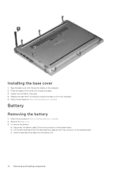
...eight M2.5 x 6 screws to secure the base cover to the computer. 5. Follow the procedure in Before working inside your computer. Battery Removing the battery 1. Follow the procedure in After working inside your computer. 2. Align the base cover with the screw holders on the system board. ... 4. b) Lift the latch and disconnect the hard disk drive cable [2] from the connector on the system board. To remove the battery: a) Disconnect the battery cable [1] from the connector on the computer. 2. Installing the base cover 1. c) Peel the hard disk drive cable from the...
...eight M2.5 x 6 screws to secure the base cover to the computer. 5. Follow the procedure in Before working inside your computer. Battery Removing the battery 1. Follow the procedure in After working inside your computer. 2. Align the base cover with the screw holders on the system board. ... 4. b) Lift the latch and disconnect the hard disk drive cable [2] from the connector on the system board. To remove the battery: a) Disconnect the battery cable [1] from the connector on the computer. 2. Installing the base cover 1. c) Peel the hard disk drive cable from the...
Ownerss Manual
Page 11
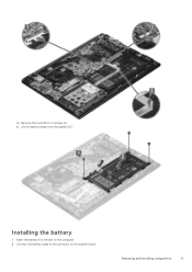
Removing and installing components 11 Insert the battery into the slot on the system board. Connect the battery cable to the connector on the computer. 2. e) Lift the battery away from the system [2]. d) Remove the four M2.0 x 3 screws [1]. Installing the battery 1.
Removing and installing components 11 Insert the battery into the slot on the system board. Connect the battery cable to the connector on the computer. 2. e) Lift the battery away from the system [2]. d) Remove the four M2.0 x 3 screws [1]. Installing the battery 1.
Ownerss Manual
Page 12
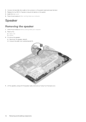
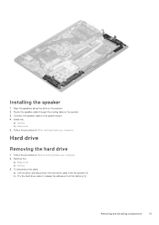
... the speaker: a) Disconnect the speaker cable [1]. 3. Follow the procedure in Before working inside your computer. Install the base cover. 6. Remove the: a) base cover b) battery 3. Follow the procedure in After working inside your computer. 2. Lift the speakers, along with the speaker cable, and remove it away from routing channel [2]. 4. Connect... the hard disk drive cable to the system. 5. Replace the four M2.0 x 3 screws to secure the battery to the connector on the system board and close the latch. 4.
... the speaker: a) Disconnect the speaker cable [1]. 3. Follow the procedure in Before working inside your computer. Install the base cover. 6. Remove the: a) base cover b) battery 3. Follow the procedure in After working inside your computer. 2. Lift the speakers, along with the speaker cable, and remove it away from routing channel [2]. 4. Connect... the hard disk drive cable to the system. 5. Replace the four M2.0 x 3 screws to secure the battery to the connector on the system board and close the latch. 4.
Ownerss Manual
Page 13
... the slots on the system. 3. To disconnect the cable: a) Lift the latch, and disconnect the hard drive cable from the battery [2]. Hard drive Removing the hard drive 1. Remove the: a) base cover b) battery 3. Removing and installing components 13 Route the speaker cable through the routing tabs on the system. 2. Connect the speaker cable...
... the slots on the system. 3. To disconnect the cable: a) Lift the latch, and disconnect the hard drive cable from the battery [2]. Hard drive Removing the hard drive 1. Remove the: a) base cover b) battery 3. Removing and installing components 13 Route the speaker cable through the routing tabs on the system. 2. Connect the speaker cable...
Ownerss Manual
Page 15
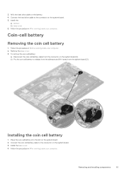
... adhesive and lift it away from the connector on the battery. 4. b) Pry the coin cell battery to the connector on the system board. 5. 3. Coin-cell battery Removing the coin cell battery 1. Remove the base cover. 3. To remove the coin cell battery: a) Disconnect the coin cell battery cable from the system board [2]. Follow the procedure in After...
... adhesive and lift it away from the connector on the battery. 4. b) Pry the coin cell battery to the connector on the system board. 5. 3. Coin-cell battery Removing the coin cell battery 1. Remove the base cover. 3. To remove the coin cell battery: a) Disconnect the coin cell battery cable from the system board [2]. Follow the procedure in After...
Ownerss Manual
Page 26
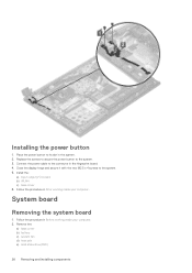
... the power button to the system. 5. Follow the procedure in Before working inside your computer. System board Removing the system board 1. Remove the: a) base cover b) battery c) system fan d) heat sink e) solid-state drive(SSD) 26 Removing and installing components
... the power button to the system. 5. Follow the procedure in Before working inside your computer. System board Removing the system board 1. Remove the: a) base cover b) battery c) system fan d) heat sink e) solid-state drive(SSD) 26 Removing and installing components
Ownerss Manual
Page 29
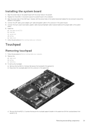
... and lift the touchpad away from the connector in the system board. 5. Install the: a) solid state drive(SSD) b) heat sink c) system fan d) battery e) base cover 7. Remove the: a) base cover b) battery c) hard drive 3. b) Disconnect the touchpad cable from system [1, 2]. Removing and installing components 29 Align the screw holes on the system board with...
... and lift the touchpad away from the connector in the system board. 5. Install the: a) solid state drive(SSD) b) heat sink c) system fan d) battery e) base cover 7. Remove the: a) base cover b) battery c) hard drive 3. b) Disconnect the touchpad cable from system [1, 2]. Removing and installing components 29 Align the screw holes on the system board with...
Ownerss Manual
Page 30
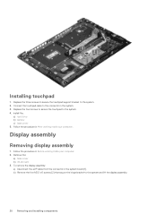
... screws to secure the touchpad support bracket to the system. 4. Display assembly Removing display assembly 1. Remove the: a) base cover b) WLAN card 3. Install the: a) hard drive b) battery c) base cover 5. Follow the procedure in the system board [1]. Replace the four screws to secure the touchpad to the system. 2. To remove the display assembly...
... screws to secure the touchpad support bracket to the system. 4. Display assembly Removing display assembly 1. Remove the: a) base cover b) WLAN card 3. Install the: a) hard drive b) battery c) base cover 5. Follow the procedure in the system board [1]. Replace the four screws to secure the touchpad to the system. 2. To remove the display assembly...
Ownerss Manual
Page 39
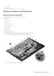
... keyboard 1. Removing and installing components 39 Follow the procedure in After working inside your computer. 2. Follow the procedure in the system [2]. Remove the: a) base cover b) battery c) system fan d) heat sink e) solid state drive(SSD) f) WLAN card g) Input output(I/O) board h) power button i) hard drive j) system board k) display assembly 3. To remove the keyboard...
... keyboard 1. Removing and installing components 39 Follow the procedure in After working inside your computer. 2. Follow the procedure in the system [2]. Remove the: a) base cover b) battery c) system fan d) heat sink e) solid state drive(SSD) f) WLAN card g) Input output(I/O) board h) power button i) hard drive j) system board k) display assembly 3. To remove the keyboard...
Ownerss Manual
Page 41
... installing components 41 Follow the procedure in Before working inside your computer. Follow the procedure in After working inside your computer. 2. Remove the: a) base cover b) battery c) speaker d) touchpad e) system fan f) heat sink g) solid state drive(SSD) h) WLAN card i) Input output(I /O) board f) WLAN card g) solid state drive(SSD) h) heat sink i) system fan...
... installing components 41 Follow the procedure in Before working inside your computer. Follow the procedure in After working inside your computer. 2. Remove the: a) base cover b) battery c) speaker d) touchpad e) system fan f) heat sink g) solid state drive(SSD) h) WLAN card i) Input output(I /O) board f) WLAN card g) solid state drive(SSD) h) heat sink i) system fan...
Ownerss Manual
Page 42
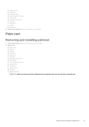
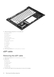
... rest: a) display assembly b) keyboard c) system board d) hard drive e) powered button f) Input Output(I/O) board g) WLAN card h) solid state drive(SSD) i) heat sink j) system fan k) touchpad l) speaker m) battery n) base cover 4. Remove the: a) base cover b) WLAN card c) display assembly d) display bezel e) camera f) display panel g) display hinge 3. Unroute the eDP cable from the routing channel...
... rest: a) display assembly b) keyboard c) system board d) hard drive e) powered button f) Input Output(I/O) board g) WLAN card h) solid state drive(SSD) i) heat sink j) system fan k) touchpad l) speaker m) battery n) base cover 4. Remove the: a) base cover b) WLAN card c) display assembly d) display bezel e) camera f) display panel g) display hinge 3. Unroute the eDP cable from the routing channel...
Ownerss Manual
Page 48
... data across the connection. And this power can support various exciting new USB standard like USB 3.1 and USB power delivery (USB PD). all those portable battery packs you charge your laptop from one little USB Type-C connection. To use . USB 3's theoretical bandwidth is a new, tiny physical connector. That's double the bandwidth...
... data across the connection. And this power can support various exciting new USB standard like USB 3.1 and USB power delivery (USB PD). all those portable battery packs you charge your laptop from one little USB Type-C connection. To use . USB 3's theoretical bandwidth is a new, tiny physical connector. That's double the bandwidth...
Ownerss Manual
Page 52
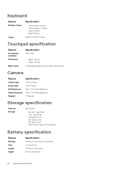
... - 5400 RPM • 1 TB - 5400 RPM • 128 GB M.2 SSD • 256 GB M.2 SSD • 512 GB M.2 SSD • HDD Free Fall Sensor (FFS) Support Battery specification Feature Wattage Type Length Height Specification 42 Whr (3 Cell) Lithium-ion/polymer Li-ion/polymer 175.36 mm (6.90 inch) 5.9 mm (0.23 inch) 52...
... - 5400 RPM • 1 TB - 5400 RPM • 128 GB M.2 SSD • 256 GB M.2 SSD • 512 GB M.2 SSD • HDD Free Fall Sensor (FFS) Support Battery specification Feature Wattage Type Length Height Specification 42 Whr (3 Cell) Lithium-ion/polymer Li-ion/polymer 175.36 mm (6.90 inch) 5.9 mm (0.23 inch) 52...
Ownerss Manual
Page 53
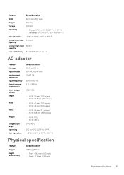
...° F) Non-Operating -20° C to 60° C (4° F to 140° F) Typical Amp-hour 3.684Ahr capacity Typical Watt-hour 42 Whr capacity Coin-cell battery 3 V CR2032 lithium ion cell AC adapter Feature Wattage Input voltage Input current (maximum) Input frequency Output current (continuous) Rated output voltage Height Width Depth Weight...
...° F) Non-Operating -20° C to 60° C (4° F to 140° F) Typical Amp-hour 3.684Ahr capacity Typical Watt-hour 42 Whr capacity Coin-cell battery 3 V CR2032 lithium ion cell AC adapter Feature Wattage Input voltage Input current (maximum) Input frequency Output current (continuous) Rated output voltage Height Width Depth Weight...


