User Manual
Page 1
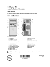
... Type: D10M002 2011 - 10 microphone connector 6. headphone connector 7. security cable slot 20. expansion card slots (4) 19. media card readers (optional) 5. USB 3.0 connectors (2) 12. power connector 17. Front And Back View Figure 1. padlock slot NOTE: The second CD/DVD drive eject button is functional only if a ...second CD/DVD drive is installed in the computer. CD/DVD drive 2. Front And Back View 1. front panel door (open ) 8. back panel connectors 18. Dell Vostro 470 Setup And Features ...
... Type: D10M002 2011 - 10 microphone connector 6. headphone connector 7. security cable slot 20. expansion card slots (4) 19. media card readers (optional) 5. USB 3.0 connectors (2) 12. power connector 17. Front And Back View Figure 1. padlock slot NOTE: The second CD/DVD drive eject button is functional only if a ...second CD/DVD drive is installed in the computer. CD/DVD drive 2. Front And Back View 1. front panel door (open ) 8. back panel connectors 18. Dell Vostro 470 Setup And Features ...
Owner's Manual
Page 12
Installing The Expansion Card 1. Follow the procedures in After Working Inside Your Computer. 12 Push the expansion card into the card slot and secure the latch. 2. Install the cover. 4. Install the expansion card retainer module to the chassis. 3.
Installing The Expansion Card 1. Follow the procedures in After Working Inside Your Computer. 12 Push the expansion card into the card slot and secure the latch. 2. Install the cover. 4. Install the expansion card retainer module to the chassis. 3.
Owner's Manual
Page 16
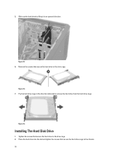
Installing The Hard Disk Drive 1. Pry the hard drive cage in an upward direction. Place the hard drive into the slot and tighten the screws that secure the hard drive to the chassis. 16 Slide out the hard drive by lifting it in the direction indicated to the drive cage. Figure 12. 6. Figure 13. 7. Tighten the screws that secure the hard drive cage to the drive cage. 2. Figure 14. 5. Remove the screws that secure the hard drive to remove the hard drive from the hard drive cage.
Installing The Hard Disk Drive 1. Pry the hard drive cage in an upward direction. Place the hard drive into the slot and tighten the screws that secure the hard drive to the chassis. 16 Slide out the hard drive by lifting it in the direction indicated to the drive cage. Figure 12. 6. Figure 13. 7. Tighten the screws that secure the hard drive cage to the drive cage. 2. Figure 14. 5. Remove the screws that secure the hard drive to remove the hard drive from the hard drive cage.
Owner's Manual
Page 23
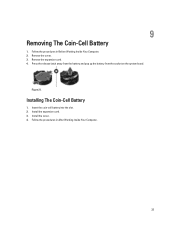
Remove the expansion card. 4. Press the release latch away from the battery and pop up the battery from the socket on the system board. Follow the procedures in Before Working Inside Your Computer. 2. Follow the procedures in After Working Inside Your Computer. 23 Installing The Coin-Cell Battery 1. Insert the coin-cell battery into the slot. 2. Install the cover. 4. Remove the cover. 3. Install the expansion card. 3. Figure 21. 9 Removing The Coin-Cell Battery 1.
Remove the expansion card. 4. Press the release latch away from the battery and pop up the battery from the socket on the system board. Follow the procedures in Before Working Inside Your Computer. 2. Follow the procedures in After Working Inside Your Computer. 23 Installing The Coin-Cell Battery 1. Insert the coin-cell battery into the slot. 2. Install the cover. 4. Remove the cover. 3. Install the expansion card. 3. Figure 21. 9 Removing The Coin-Cell Battery 1.

Owner's Manual
Page 39
Removing The WLAN Card 1. Remove the cover. 3. Release the WLAN card cable from the card slot. 15 Figure 38. 6. Remove the WLAN card cable from the computer by sliding it from the routing clips and lift them in Before Working Inside Your Computer. 2. Remove the front bezel. 4. Figure 39. 7. Follow the procedures in an upward direction. Disconnect the antenna cables from the front of the computer. 39 Remove the screw that secures the WLAN card and remove it around from the WLAN card. 5.
Removing The WLAN Card 1. Remove the cover. 3. Release the WLAN card cable from the card slot. 15 Figure 38. 6. Remove the WLAN card cable from the computer by sliding it from the routing clips and lift them in Before Working Inside Your Computer. 2. Remove the front bezel. 4. Figure 39. 7. Follow the procedures in an upward direction. Disconnect the antenna cables from the front of the computer. 39 Remove the screw that secures the WLAN card and remove it around from the WLAN card. 5.

Owner's Manual
Page 40
Figure 40. Follow the procedures in place. 4. Slide the WLAN card into its slot. 3. Install the cover. 7. Tighten the screws to the color code on the WLAN card. 5. Installing The WLAN Card 1. Install the front bezel. 6. Connect the antenna cables according to secure the WLAN card in After Working Inside Your Computer. 40 Route the WLAN card cable around the securing clips. 2.
Figure 40. Follow the procedures in place. 4. Slide the WLAN card into its slot. 3. Install the cover. 7. Tighten the screws to the color code on the WLAN card. 5. Installing The WLAN Card 1. Install the front bezel. 6. Connect the antenna cables according to secure the WLAN card in After Working Inside Your Computer. 40 Route the WLAN card cable around the securing clips. 2.


