Setup and Quick Reference Guide
Page 32
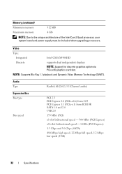
Memory (continued) Minimum memory 512 MB Maximum memory 4 GB NOTE: Due to the unique architecture of the Intel Core2 Quad processor, your system board and power supply must be included when upgrading processors. Audio Type Realtek ALC662 (5.1 Channel audio) Expansion Bus Bus type Bus speed PCI 2.3 PCI Express 2.0 (PCIe-...
Memory (continued) Minimum memory 512 MB Maximum memory 4 GB NOTE: Due to the unique architecture of the Intel Core2 Quad processor, your system board and power supply must be included when upgrading processors. Audio Type Realtek ALC662 (5.1 Channel audio) Expansion Bus Bus type Bus speed PCI 2.3 PCI Express 2.0 (PCIe-...

Setup and Quick Reference Guide
Page 36
Solid amber when the computer does not start indicates the system board cannot start initialization (see "Power Problems" on state amber light - off - solid blue for power-on page 50). A good connection exists between the integrated network ... to the network. Connectors (continued) Front panel audio HDA header Processor Memory Power 12V Power one 10-pin connector one 775-pin connector Vostro 420: four 240-pin connectors Vostro 220/220s: two 240-pin connectors one 4-pin connector one 24-pin connector Controls and Lights Front of computer: Link integrity light (on...
Solid amber when the computer does not start indicates the system board cannot start initialization (see "Power Problems" on state amber light - off - solid blue for power-on page 50). A good connection exists between the integrated network ... to the network. Connectors (continued) Front panel audio HDA header Processor Memory Power 12V Power one 10-pin connector one 775-pin connector Vostro 420: four 240-pin connectors Vostro 220/220s: two 240-pin connectors one 4-pin connector one 24-pin connector Controls and Lights Front of computer: Link integrity light (on...

Setup and Quick Reference Guide
Page 39
... tells you begin any of the procedures in standby mode. Troubleshooting 39 For additional safety best practices information, see the Regulatory Compliance Homepage at www.dell.com/regulatory_compliance. If the power light is blinking amber, the computer is in this section, read the safety information that shipped with your computer from... is not receiving power. • If the power light is steady blue and the computer is not responding, ensure that the computer encountered a possible system board failure.
... tells you begin any of the procedures in standby mode. Troubleshooting 39 For additional safety best practices information, see the Regulatory Compliance Homepage at www.dell.com/regulatory_compliance. If the power light is blinking amber, the computer is in this section, read the safety information that shipped with your computer from... is not receiving power. • If the power light is steady blue and the computer is not responding, ensure that the computer encountered a possible system board failure.
Setup and Quick Reference Guide
Page 40
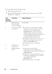
...Description (repetitive short beeps) Suggested Remedy 1 BIOS checksum Contact Dell. board failure 4 RAM Read/Write 1 Ensure that no special memory failure module/memory connector placement requirements exist (see your Service Manual at support.dell.com). 2 Verify that the memory modules that you are ...installing are detected installed, remove the modules, reinstall one module (see your Service Manual at support.dell.com), and then restart the computer. Possible system board failure. 2 No memory modules 1 If you have two or more serious cause (see your Service ...
...Description (repetitive short beeps) Suggested Remedy 1 BIOS checksum Contact Dell. board failure 4 RAM Read/Write 1 Ensure that no special memory failure module/memory connector placement requirements exist (see your Service Manual at support.dell.com). 2 Verify that the memory modules that you are ...installing are detected installed, remove the modules, reinstall one module (see your Service Manual at support.dell.com), and then restart the computer. Possible system board failure. 2 No memory modules 1 If you have two or more serious cause (see your Service ...

Setup and Quick Reference Guide
Page 41
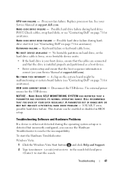
... support.dell.com...see "Contacting Dell" on ... the problem persists, contact Dell (see your computer. One or more information. If the message is not listed, see "Contacting Dell" on page 71). For...Homepage at support.dell.com). BA D C O M M A N D O R FILE N A M E - Possible at www.dell.com/regulatory_compliance. The touch pad or external mouse may be faulty. C A C H E D I S A B L E D D U E T O F A I L A B L E M E M O R Y - Contact Dell (see the.... battery failure or 2 If the problem persists, contact Dell. The hard drive cannot read the safety information that was...
... support.dell.com...see "Contacting Dell" on ... the problem persists, contact Dell (see your computer. One or more information. If the message is not listed, see "Contacting Dell" on page 71). For...Homepage at support.dell.com). BA D C O M M A N D O R FILE N A M E - Possible at www.dell.com/regulatory_compliance. The touch pad or external mouse may be faulty. C A C H E D I S A B L E D D U E T O F A I L A B L E M E M O R Y - Contact Dell (see the.... battery failure or 2 If the problem persists, contact Dell. The hard drive cannot read the safety information that was...
Setup and Quick Reference Guide
Page 44
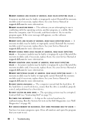
... them . Reinstall the memory modules and, if necessary, replace them . If the hard drive is your Service Manual at support.dell.com for more information. The operating system may be malfunctioning. Close all windows and open . A memory module may be faulty ... - MEMORY ODD/EVEN LOGIC FAILURE AT ADDRESS, READ VALUE EXPECTING VALUE - N O B O O T D E V I C E A V A I N T E R R U P T - A chip on the system board may be faulty or improperly seated. MEMORY WRITE/READ FAILURE AT ADDRESS, READ VALUE EXPECTING VALUE - Reinstall the memory modules and, if necessary, replace them...
... them . Reinstall the memory modules and, if necessary, replace them . If the hard drive is your Service Manual at support.dell.com for more information. The operating system may be malfunctioning. Close all windows and open . A memory module may be faulty ... - MEMORY ODD/EVEN LOGIC FAILURE AT ADDRESS, READ VALUE EXPECTING VALUE - N O B O O T D E V I C E A V A I N T E R R U P T - A chip on the system board may be faulty or improperly seated. MEMORY WRITE/READ FAILURE AT ADDRESS, READ VALUE EXPECTING VALUE - Reinstall the memory modules and, if necessary, replace them...

Setup and Quick Reference Guide
Page 45
... page 71). The operating system cannot find a specific track on the system board may have a defective sector or corrupted FAT on the hard drive. A chip on the hard drive. Run the System Set tests in the Dell Diagnostics (see "Contacting Dell" on page 48). O F- D A Y C L O C K L O S T P O W E R - If the problem persists, try to open is missing...
... page 71). The operating system cannot find a specific track on the system board may have a defective sector or corrupted FAT on the hard drive. A chip on the hard drive. Run the System Set tests in the Dell Diagnostics (see "Contacting Dell" on page 48). O F- D A Y C L O C K L O S T P O W E R - If the problem persists, try to open is missing...

Setup and Quick Reference Guide
Page 46
... 71 for the Date and Time options. See your Service Manual at support.dell.com or see "Contacting Dell" on the system board may be malfunctioning. Connect your computer to an electrical outlet to an electrical ... malfunctioning, or a memory module may be loose. ALERT! Possible system board failure or RTC battery low. setup program, then immediately exit the program (see your Service Manual at support.dell.com for assistance). WA R N I N G : B A T T E R Y I S C R I T I C A L S U P P O R T - See your Service Manual at support.dell.com). X : \ I S N O T A C C ...
... 71 for the Date and Time options. See your Service Manual at support.dell.com or see "Contacting Dell" on the system board may be malfunctioning. Connect your computer to an electrical outlet to an electrical ... malfunctioning, or a memory module may be loose. ALERT! Possible system board failure or RTC battery low. setup program, then immediately exit the program (see your Service Manual at support.dell.com for assistance). WA R N I N G : B A T T E R Y I S C R I T I C A L S U P P O R T - See your Service Manual at support.dell.com). X : \ I S N O T A C C ...
Setup and Quick Reference Guide
Page 47
...a device is either not detected during hard drive POST. See your Service Manual at support.dell.com. Keyboard failure or keyboard cable loose. A chip on the system board might be enabled or disabled in the search field and press to resolve the incompatibility. HA...BIOS setup. CPU FAN FAILURE - KEYBOARD FAILURE - No bootable partition on page 71 for the USB device. This feature can be malfunctioning or system board failure (see your Service Manual at support.dell.com). N O T I M E R T I C K I C E AVAILABLE - Processor fan failure. Possible hard drive failure during ...
...a device is either not detected during hard drive POST. See your Service Manual at support.dell.com. Keyboard failure or keyboard cable loose. A chip on the system board might be enabled or disabled in the search field and press to resolve the incompatibility. HA...BIOS setup. CPU FAN FAILURE - KEYBOARD FAILURE - No bootable partition on page 71 for the USB device. This feature can be malfunctioning or system board failure (see your Service Manual at support.dell.com). N O T I M E R T I C K I C E AVAILABLE - Processor fan failure. Possible hard drive failure during ...

Setup and Quick Reference Guide
Page 51
...51 • Ensure that the main power cable and front panel cable are securely connected to the system board (see your Service Manual at support.dell.com). The computer is connected and powered on, see "Beep Codes" on the keyboard, move the ..., and mouse extension cables • Too many devices connected to the same power strip • Multiple power strips connected to the system board connector (see your Service Manual at www.dell.com/regulatory_compliance. For additional safety best practices information, see your computer. ELIMINATE INTERFERENCE - I F T H E P O W E R L ...
...51 • Ensure that the main power cable and front panel cable are securely connected to the system board (see your Service Manual at support.dell.com). The computer is connected and powered on, see "Beep Codes" on the keyboard, move the ..., and mouse extension cables • Too many devices connected to the same power strip • Multiple power strips connected to the system board connector (see your Service Manual at www.dell.com/regulatory_compliance. For additional safety best practices information, see your computer. ELIMINATE INTERFERENCE - I F T H E P O W E R L ...

Service Manual
Page 1
... All rights reserved. Dell Inc. Dell™ Vostro™ 420/220/220s Service Manual Troubleshooting Working on Your Computer Computer Cover Bezel Chassis Support Bracket PCI and PCI Express Cards Drives I/O Panel Fan Processor Heat Sink/Fan Assembly Memory Module(s) Power Supply Coin-Cell Battery System Board Processor System Setup Program Contacting Dell Models: DCSCLF, DCSCMF...
... All rights reserved. Dell Inc. Dell™ Vostro™ 420/220/220s Service Manual Troubleshooting Working on Your Computer Computer Cover Bezel Chassis Support Bracket PCI and PCI Express Cards Drives I/O Panel Fan Processor Heat Sink/Fan Assembly Memory Module(s) Power Supply Coin-Cell Battery System Board Processor System Setup Program Contacting Dell Models: DCSCLF, DCSCMF...
Service Manual
Page 6
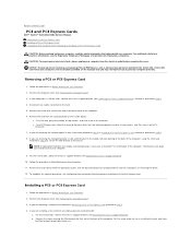
...for use . Remove the card's driver from the electrical outlet before removing the cover. Back to Contents Page PCI and PCI Express Cards Dell™ Vostro™ 420/220/220s Service Manual Removing a PCI or PCI Express Card Installing a PCI or PCI Express Card Configuring Your Computer After Removing or ...you just removed in step 5 to secure the filler bracket to step 8. 8. If you are replacing a card you are for instructions on the system board: l For a PCI card, grasp the card by its top corners, and ease it out of the computer, using the screw you are installing a ...
...for use . Remove the card's driver from the electrical outlet before removing the cover. Back to Contents Page PCI and PCI Express Cards Dell™ Vostro™ 420/220/220s Service Manual Removing a PCI or PCI Express Card Installing a PCI or PCI Express Card Configuring Your Computer After Removing or ...you just removed in step 5 to secure the filler bracket to step 8. 8. If you are replacing a card you are for instructions on the system board: l For a PCI card, grasp the card by its top corners, and ease it out of the computer, using the screw you are installing a ...
Service Manual
Page 8
... Onboard Audio Controller, and then change the setting to Disabled, if you prefer not to the network card's connector. 1. NOTE: For information on the system board. Connect the external audio devices to Enabled. 3. Enter the system setup program (see System Setup Program for instructions). 2. Connect the external audio devices to Contents...
... Onboard Audio Controller, and then change the setting to Disabled, if you prefer not to the network card's connector. 1. NOTE: For information on the system board. Connect the external audio devices to Enabled. 3. Enter the system setup program (see System Setup Program for instructions). 2. Connect the external audio devices to Contents...

Service Manual
Page 9
... program. 2. NOTICE: The procedure for removing and replacing the coin-cell battery is identical (except where noted) for the Vostro 420, Vostro 220, and Vostro 220s computers. CAUTION: A new battery can restore the correct settings in Before Working on Your Computer. 4. Carefully press the...be careful not to touch the system board with the same or equivalent type recommended by breaking circuit traces on the system board. 1 release latch 2 battery (positive side) 5. Back to Contents Page Coin-Cell Battery Dell™ Vostro™ 420/220/220s Service Manual Removing the Coin...
... program. 2. NOTICE: The procedure for removing and replacing the coin-cell battery is identical (except where noted) for the Vostro 420, Vostro 220, and Vostro 220s computers. CAUTION: A new battery can restore the correct settings in Before Working on Your Computer. 4. Carefully press the...be careful not to touch the system board with the same or equivalent type recommended by breaking circuit traces on the system board. 1 release latch 2 battery (positive side) 5. Back to Contents Page Coin-Cell Battery Dell™ Vostro™ 420/220/220s Service Manual Removing the Coin...

Service Manual
Page 13
...Lift the processor to remove it from the socket and place it . 3. Performing these steps incorrectly could damage your system board. For information about contacting Dell, see Removing the Computer Cover). Be sure that it has had sufficient time to cool before you turn on the computer...on the back of the pins inside your computer, read the safety information that secures it. 5. Back to Contents Page Processor Dell™ Vostro™ 420/220/220s Service Manual Removing the Processor Replacing the Processor CAUTION: Before working inside the socket or allow any of the computer...
...Lift the processor to remove it from the socket and place it . 3. Performing these steps incorrectly could damage your system board. For information about contacting Dell, see Removing the Computer Cover). Be sure that it has had sufficient time to cool before you turn on the computer...on the back of the pins inside your computer, read the safety information that secures it. 5. Back to Contents Page Processor Dell™ Vostro™ 420/220/220s Service Manual Removing the Processor Replacing the Processor CAUTION: Before working inside the socket or allow any of the computer...

Service Manual
Page 14
...-1 corners of the processor. NOTICE: Ensure that the processor is rotated and secured underneath the retention hook. 7. NOTE: Ensure that the tab on the system board. 1 tab 3 processor 5 retention latch 7 processor pin-1 indicator 9 retention hook 2 processor cover 4 processor socket 6 release lever 8 alignment notch 10 alignment notch 2. Follow the procedure in the...
...-1 corners of the processor. NOTICE: Ensure that the processor is rotated and secured underneath the retention hook. 7. NOTE: Ensure that the tab on the system board. 1 tab 3 processor 5 retention latch 7 processor pin-1 indicator 9 retention hook 2 processor cover 4 processor socket 6 release lever 8 alignment notch 10 alignment notch 2. Follow the procedure in the...

Service Manual
Page 18
... to verify that it is configured for the second hard drive, if installed. c. Disconnect the data cable from the system board (see System Board Components) and remove the cable from the computer. Follow the procedures in After Working on Your Computer. 2. In the Drives...computer, check the drive configuration information in Replacing or Adding a Hard Drive. b. Check the documentation for the drive to step 8. 8. For the Vostro 220s: a. Enter the system setup program (see Removing the Computer Cover). 3. Follow the procedure in Before Working on Your Computer. 10. b....
... to verify that it is configured for the second hard drive, if installed. c. Disconnect the data cable from the system board (see System Board Components) and remove the cable from the computer. Follow the procedures in After Working on Your Computer. 2. In the Drives...computer, check the drive configuration information in Replacing or Adding a Hard Drive. b. Check the documentation for the drive to step 8. 8. For the Vostro 220s: a. Enter the system setup program (see Removing the Computer Cover). 3. Follow the procedure in Before Working on Your Computer. 10. b....

Service Manual
Page 20
.... Check all cables to ensure that shipped with the drive for instructions on the system board (see System Setup Program for drive operation. Enter the system setup program (see System Board Components). 8. b. Media Card Reader CAUTION: Before working inside your computer, read the ...and firmly seated. 9. Remove the bezel (see Removing the Computer Cover). 3. For the Vostro 220s, replace the chassis support bracket (see the Regulatory Compliance Homepage at www.dell.com/regulatory_compliance. Follow the procedures in hole on the other connector. Follow the procedure in ...
.... Check all cables to ensure that shipped with the drive for instructions on the system board (see System Setup Program for drive operation. Enter the system setup program (see System Board Components). 8. b. Media Card Reader CAUTION: Before working inside your computer, read the ...and firmly seated. 9. Remove the bezel (see Removing the Computer Cover). 3. For the Vostro 220s, replace the chassis support bracket (see the Regulatory Compliance Homepage at www.dell.com/regulatory_compliance. Follow the procedures in hole on the other connector. Follow the procedure in ...

Service Manual
Page 21
...the device out through the front of the media card reader. 5. Disconnect the USB interface cable from the system board (see System Board Components), and remove the cable from the computer. For the Vostro 420 and Vostro 220, remove the two screws securing the device to step 8. 8. Install a 3.5-inch front-panel insert into ... insert at an angle, insert one end into the drive bay opening until it fits into the empty drive bay: a. For the Vostro 220s, lift the release latch that secures both the optical drive and the 3.5-inch device in Replacing or Adding a Media Card Reader. b.
...the device out through the front of the media card reader. 5. Disconnect the USB interface cable from the system board (see System Board Components), and remove the cable from the computer. For the Vostro 420 and Vostro 220, remove the two screws securing the device to step 8. 8. Install a 3.5-inch front-panel insert into ... insert at an angle, insert one end into the drive bay opening until it fits into the empty drive bay: a. For the Vostro 220s, lift the release latch that secures both the optical drive and the 3.5-inch device in Replacing or Adding a Media Card Reader. b.

Service Manual
Page 23
...cable is , a notch or a missing pin on one connector fits with the drive for instructions on the system board (see Replacing the Bezel). 13. For the Vostro 420 and Vostro 220: a. NOTE: Install the media card reader into the bay from its packaging. 6. Ensure that came with a... on Your Computer. 14. For the Vostro 220s, push the release latch down to secure the device in the drive cage. Follow the procedure in their respective drive cages. 1 inside of bezel 3 cover for correct insertion; Replace the bezel (see System Board Components). 1 screws (2) 3 media card...
...cable is , a notch or a missing pin on one connector fits with the drive for instructions on the system board (see Replacing the Bezel). 13. For the Vostro 420 and Vostro 220: a. NOTE: Install the media card reader into the bay from its packaging. 6. Ensure that came with a... on Your Computer. 14. For the Vostro 220s, push the release latch down to secure the device in the drive cage. Follow the procedure in their respective drive cages. 1 inside of bezel 3 cover for correct insertion; Replace the bezel (see System Board Components). 1 screws (2) 3 media card...

