Setup and Quick Reference Guide
Page 4
Vostro 220s Back View 28 Vostro 220s Back Panel Connectors 29 4 Specifications 31 5 Troubleshooting 39 Tools 39 Power Lights 39 Beep Codes 39 Error Messages 41 System Messages 46 Troubleshooting Software and Hardware Problems 47 Dell Diagnostics 48 Troubleshooting Tips 50 Power Problems 50 Memory Problems 51 Lockups and Software Problems 52 Dell Technical Update Service 54 Dell Support Utility 55 6 Reinstalling Software 57 Drivers 57 Identifying Drivers 57 Reinstalling Drivers and Utilities 58 4 Contents
Vostro 220s Back View 28 Vostro 220s Back Panel Connectors 29 4 Specifications 31 5 Troubleshooting 39 Tools 39 Power Lights 39 Beep Codes 39 Error Messages 41 System Messages 46 Troubleshooting Software and Hardware Problems 47 Dell Diagnostics 48 Troubleshooting Tips 50 Power Problems 50 Memory Problems 51 Lockups and Software Problems 52 Dell Technical Update Service 54 Dell Support Utility 55 6 Reinstalling Software 57 Drivers 57 Identifying Drivers 57 Reinstalling Drivers and Utilities 58 4 Contents
Setup and Quick Reference Guide
Page 31
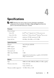
Specifications NOTE: Offerings may vary by region. Processor Processor types: Vostro 420: Vostro 220, 220s: Level 2 (L2) cache Front side bus Intel® Core™2 Quad, Core™2 Duo processors Intel Core™2 Duo, Celeron®, Pentium&#...Help and Support and select the option to view information about your computer. For more information regarding the configuration of 10/100/1000 Mbps communication Memory Type Memory connectors Memory modules supported DDR2 800 MHz SDRAM (DDR2 667 MHz capable) Vostro 420: four Vostro 220/220s: two 512 MB, 1 GB, or 2 GB Specifications 31
Specifications NOTE: Offerings may vary by region. Processor Processor types: Vostro 420: Vostro 220, 220s: Level 2 (L2) cache Front side bus Intel® Core™2 Quad, Core™2 Duo processors Intel Core™2 Duo, Celeron®, Pentium&#...Help and Support and select the option to view information about your computer. For more information regarding the configuration of 10/100/1000 Mbps communication Memory Type Memory connectors Memory modules supported DDR2 800 MHz SDRAM (DDR2 667 MHz capable) Vostro 420: four Vostro 220/220s: two 512 MB, 1 GB, or 2 GB Specifications 31
Setup and Quick Reference Guide
Page 32
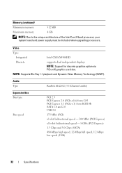
NOTE: Supports Blu-Ray 1.1 playback and Dynamic Video Memory Technology (DVMT). Audio Type Realtek ALC662 (5.1 Channel audio) Expansion Bus Bus type Bus speed PCI 2.3 PCI Express 2.0 (PCIe-x16) from G45 PCI Express 1.1 (PCIe-x1) ... speed - 8 GB/s (PCI Express) 1.5 Gbps and 3.0 Gbps (SATA) 480-Mbps high speed, 12-Mbps full speed, 1.2-Mbps low speed (USB) 32 Specifications Memory (continued) Minimum memory 512 MB Maximum memory 4 GB NOTE: Due to the unique architecture of the Intel Core2 Quad processor, your system board and power supply must be included when...
NOTE: Supports Blu-Ray 1.1 playback and Dynamic Video Memory Technology (DVMT). Audio Type Realtek ALC662 (5.1 Channel audio) Expansion Bus Bus type Bus speed PCI 2.3 PCI Express 2.0 (PCIe-x16) from G45 PCI Express 1.1 (PCIe-x1) ... speed - 8 GB/s (PCI Express) 1.5 Gbps and 3.0 Gbps (SATA) 480-Mbps high speed, 12-Mbps full speed, 1.2-Mbps low speed (USB) 32 Specifications Memory (continued) Minimum memory 512 MB Maximum memory 4 GB NOTE: Due to the unique architecture of the Intel Core2 Quad processor, your system board and power supply must be included when...

Setup and Quick Reference Guide
Page 36
... power supply unit. Network activity light (on green light - Connectors (continued) Front panel audio HDA header Processor Memory Power 12V Power one 10-pin connector one 775-pin connector Vostro 420: four 240-pin connectors Vostro 220/220s: two 240-pin connectors one 4-pin connector one 24-pin connector Controls and Lights Front of...
... power supply unit. Network activity light (on green light - Connectors (continued) Front panel audio HDA header Processor Memory Power 12V Power one 10-pin connector one 775-pin connector Vostro 420: four 240-pin connectors Vostro 220/220s: two 240-pin connectors one 4-pin connector one 24-pin connector Controls and Lights Front of...

Setup and Quick Reference Guide
Page 39
...code tells you begin any of the procedures in standby mode. For additional safety best practices information, see the Regulatory Compliance Homepage at www.dell.com/regulatory_compliance. If the power light is blinking amber, the computer is connected and powered on the keyboard, move the mouse, or ... the power light is steady blue and the computer is not responding, ensure that the display is receiving electrical power, a device such as a memory module or graphics card might emit a series of beeps during start-up if the monitor cannot display errors or problems. This series of beeps, ...
...code tells you begin any of the procedures in standby mode. For additional safety best practices information, see the Regulatory Compliance Homepage at www.dell.com/regulatory_compliance. If the power light is blinking amber, the computer is connected and powered on the keyboard, move the mouse, or ... the power light is steady blue and the computer is not responding, ensure that the display is receiving electrical power, a device such as a memory module or graphics card might emit a series of beeps during start-up if the monitor cannot display errors or problems. This series of beeps, ...
Setup and Quick Reference Guide
Page 40
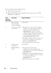
...installing are detected installed, remove the modules, reinstall one module (see your Service Manual at support.dell.com), and then restart the computer. Possible system board failure. 2 No memory modules 1 If you have identified a faulty module or reinstalled all modules without error. 2 If... available, install good memory of the same type into your computer see your Service Manual at support.dell.com). 3 If the problem persists, contact Dell. 3 Possible system Contact Dell. If your computer beeps during start-up: 1 Write down the ...
...installing are detected installed, remove the modules, reinstall one module (see your Service Manual at support.dell.com), and then restart the computer. Possible system board failure. 2 No memory modules 1 If you have identified a faulty module or reinstalled all modules without error. 2 If... available, install good memory of the same type into your computer see your Service Manual at support.dell.com). 3 If the problem persists, contact Dell. 3 Possible system Contact Dell. If your computer beeps during start-up: 1 Write down the ...

Setup and Quick Reference Guide
Page 41
...See your Service Manual at support.dell.com for more information. If the message is not listed, see the documentation for more information. DATA ERROR - One or more memory modules may be faulty or improperly seated. Reinstall the memory modules and, if necessary, replace... them. Possible at www.dell.com/regulatory_compliance. failure Error Messages CAUTION: Before you have spelled the command...
...See your Service Manual at support.dell.com for more information. If the message is not listed, see the documentation for more information. DATA ERROR - One or more memory modules may be faulty or improperly seated. Reinstall the memory modules and, if necessary, replace... them. Possible at www.dell.com/regulatory_compliance. failure Error Messages CAUTION: Before you have spelled the command...
Setup and Quick Reference Guide
Page 42
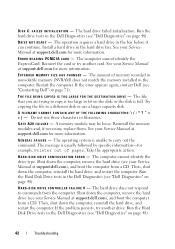
...Service Manual at support.dell.com for example, Printer out of memory recorded in nonvolatile memory (NVRAM) does not match the memory installed in the Dell Diagnostics (see your Service Manual at support.dell.com for more information.... A I Z E H A S C H A N G E D - DRIVE NOT READY - Install a hard drive in the bay before it can continue. If the error appears again, contact Dell (see your Service Manual at support.dell.com), and boot the computer from the computer. Reinstall the memory modules and, if necessary, replace them. ERROR READING PCMCIA CARD - The amount of paper...
...Service Manual at support.dell.com for example, Printer out of memory recorded in nonvolatile memory (NVRAM) does not match the memory installed in the Dell Diagnostics (see your Service Manual at support.dell.com for more information.... A I Z E H A S C H A N G E D - DRIVE NOT READY - Install a hard drive in the bay before it can continue. If the error appears again, contact Dell (see your Service Manual at support.dell.com), and boot the computer from the computer. Reinstall the memory modules and, if necessary, replace them. ERROR READING PCMCIA CARD - The amount of paper...

Setup and Quick Reference Guide
Page 43
...Key test in the Dell Diagnostics (see "Dell Diagnostics" on page 48). If the problem persists, try another drive. HA R D - Then, shut down the computer, reinstall the hard drive, and restart the computer. The operating system is trying to boot to occur after a memory module is most ...likely to nonbootable media, such as a floppy disk or CD. INVALID CONFIGURATION INFORMATION-PLEASE RUN SYSTEM SETUP PROGRAM - See your Service Manual at support.dell.com for more information. For external keyboards, check the ...
...Key test in the Dell Diagnostics (see "Dell Diagnostics" on page 48). If the problem persists, try another drive. HA R D - Then, shut down the computer, reinstall the hard drive, and restart the computer. The operating system is trying to boot to occur after a memory module is most ...likely to nonbootable media, such as a floppy disk or CD. INVALID CONFIGURATION INFORMATION-PLEASE RUN SYSTEM SETUP PROGRAM - See your Service Manual at support.dell.com for more information. For external keyboards, check the ...
Setup and Quick Reference Guide
Page 44
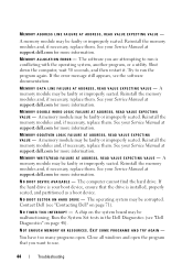
... AT ADDRESS, READ VALUE EXPECTING VALUE - See your Service Manual at support.dell.com for more information. See your Service Manual at support.dell.com for more information. Reinstall the memory modules and, if necessary, replace them . The computer cannot find the hard...the hard drive is your Service Manual at support.dell.com for more information. N O T I M E R T I C K I V E - NOT ENOUGH MEMORY OR RESOURCES. MEMORY ADDRESS LINE FAILURE AT ADDRESS, READ VALUE EXPECTING VALUE - If the error message still appears, see "Contacting Dell" on page 71). See your boot device,...
... AT ADDRESS, READ VALUE EXPECTING VALUE - See your Service Manual at support.dell.com for more information. See your Service Manual at support.dell.com for more information. Reinstall the memory modules and, if necessary, replace them . The computer cannot find the hard...the hard drive is your Service Manual at support.dell.com for more information. N O T I M E R T I C K I V E - NOT ENOUGH MEMORY OR RESOURCES. MEMORY ADDRESS LINE FAILURE AT ADDRESS, READ VALUE EXPECTING VALUE - If the error message still appears, see "Contacting Dell" on page 71). See your boot device,...

Setup and Quick Reference Guide
Page 46
...the problem persists, contact Dell (see "Dell Diagnostics" on page 71). The time or date stored in the table, see "Contacting Dell" on page 71 for the Date and Time options. See your Service Manual at support.dell.com). Run the System Memory tests and the Keyboard ...Controller test in the Dell Diagnostics (see "Dell Diagnostics" on page 71). T H E D E V I C E I C A L S U P P O R T - Insert a disk into the drive and try again. The battery...
...the problem persists, contact Dell (see "Dell Diagnostics" on page 71). The time or date stored in the table, see "Contacting Dell" on page 71 for the Date and Time options. See your Service Manual at support.dell.com). Run the System Memory tests and the Keyboard ...Controller test in the Dell Diagnostics (see "Dell Diagnostics" on page 71). T H E D E V I C E I C A L S U P P O R T - Insert a disk into the drive and try again. The battery...

Setup and Quick Reference Guide
Page 51
... cables • Too many devices connected to the same power strip • Multiple power strips connected to the same electrical outlet Memory Problems CAUTION: Before you begin any expansion cards, including graphics cards (see "Beep Codes" on the keyboard, move the mouse,... is a power problem, a device may be malfunctioning or incorrectly installed. • Remove and then reinstall all memory modules (see your Service Manual at www.dell.com/regulatory_compliance. Some possible causes of interference are securely connected to the system board connector (see your Service Manual ...
... cables • Too many devices connected to the same power strip • Multiple power strips connected to the same electrical outlet Memory Problems CAUTION: Before you begin any expansion cards, including graphics cards (see "Beep Codes" on the keyboard, move the mouse,... is a power problem, a device may be malfunctioning or incorrectly installed. • Remove and then reinstall all memory modules (see your Service Manual at www.dell.com/regulatory_compliance. Some possible causes of interference are securely connected to the system board connector (see your Service Manual ...
Setup and Quick Reference Guide
Page 52
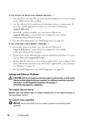
...stops responding NOTICE: You may lose data if you are unable to see if that the memory you are following the memory installation guidelines (see the Regulatory Compliance Homepage at www.dell.com/regulatory_compliance. For more information about the type of the procedures in this section, read the... safety information that your computer, see "Memory" on page 31. • Run the Dell Diagnostics (see "Dell Diagnostics" on page 48). IF YOU RECEIVE AN INSUFFICIENT MEMORY MESSAGE - • Save and close any open programs you are not using is ...
...stops responding NOTICE: You may lose data if you are unable to see if that the memory you are following the memory installation guidelines (see the Regulatory Compliance Homepage at www.dell.com/regulatory_compliance. For more information about the type of the procedures in this section, read the... safety information that your computer, see "Memory" on page 31. • Run the Dell Diagnostics (see "Dell Diagnostics" on page 48). IF YOU RECEIVE AN INSUFFICIENT MEMORY MESSAGE - • Save and close any open programs you are not using is ...

Setup and Quick Reference Guide
Page 74
... and Settings Transfer Wizard, 17 finding information, 7 I Internet connecting, 16 setting up, 16 L license label, 8 M media Drivers and Utilities, 7 operating system, 7 memory troubleshooting, 51 N networks, 13 connecting, 13 O operating system Dell Factory Image Restore, 62 media, 63 reinstalling, 7 System Restore, 60 Operating System media, 7 operating system product key, 8 P phone numbers, 71 power...
... and Settings Transfer Wizard, 17 finding information, 7 I Internet connecting, 16 setting up, 16 L license label, 8 M media Drivers and Utilities, 7 operating system, 7 memory troubleshooting, 51 N networks, 13 connecting, 13 O operating system Dell Factory Image Restore, 62 media, 63 reinstalling, 7 System Restore, 60 Operating System media, 7 operating system product key, 8 P phone numbers, 71 power...
Setup and Quick Reference Guide
Page 75
... connectors, 34 controls and lights, 36 drives, 34 environmental, 38 expansion bus, 32 memory, 31 physical, 37 power, 37 processor, 31 system information, 31 video, 32 support, 65 contacting Dell, 71 DellConnect, 66 online services, 66 regional, 66 technical support and customer service, 66... and Conditions, 8 transferring information to a new computer, 17 troubleshooting, 8, 39 blue screen, 54 computer not responding, 52 Dell Diagnostics, 48 error messages, 41 memory, 51 power, 50 power light conditions, 50 power lights, 39 program crashes, 52 programs and Windows compatibility, 53 restore to...
... connectors, 34 controls and lights, 36 drives, 34 environmental, 38 expansion bus, 32 memory, 31 physical, 37 power, 37 processor, 31 system information, 31 video, 32 support, 65 contacting Dell, 71 DellConnect, 66 online services, 66 regional, 66 technical support and customer service, 66... and Conditions, 8 transferring information to a new computer, 17 troubleshooting, 8, 39 blue screen, 54 computer not responding, 52 Dell Diagnostics, 48 error messages, 41 memory, 51 power, 50 power light conditions, 50 power lights, 39 program crashes, 52 programs and Windows compatibility, 53 restore to...

Service Manual
Page 1
...CAUTION: A CAUTION indicates potential for property damage, personal injury, or death. and other than its own. Dell™ Vostro™ 420/220/220s Service Manual Troubleshooting Working on Your Computer Computer Cover Bezel Chassis Support Bracket PCI and PCI Express ...Cards Drives I/O Panel Fan Processor Heat Sink/Fan Assembly Memory Module(s) Power Supply Coin-Cell Battery System Board Processor System Setup Program Contacting Dell...
...CAUTION: A CAUTION indicates potential for property damage, personal injury, or death. and other than its own. Dell™ Vostro™ 420/220/220s Service Manual Troubleshooting Working on Your Computer Computer Cover Bezel Chassis Support Bracket PCI and PCI Express ...Cards Drives I/O Panel Fan Processor Heat Sink/Fan Assembly Memory Module(s) Power Supply Coin-Cell Battery System Board Processor System Setup Program Contacting Dell...

Service Manual
Page 35
... start properly. Back to Contents Page Memory Module(s) Dell™ Vostro™ 420/220/220s Service Manual Removing Memory Modules Replacing or Adding a Memory Module CAUTION: Before working inside your computer, read the safety information that you install a single memory module in DIMM connector 1, the connector closest to remove it upwards. NOTE: Vostro 420 can accommodate two DIMMs. 1 Pair...
... start properly. Back to Contents Page Memory Module(s) Dell™ Vostro™ 420/220/220s Service Manual Removing Memory Modules Replacing or Adding a Memory Module CAUTION: Before working inside your computer, read the safety information that you install a single memory module in DIMM connector 1, the connector closest to remove it upwards. NOTE: Vostro 420 can accommodate two DIMMs. 1 Pair...

Service Manual
Page 36
... module. 2. Log on Your Computer. 4. Back to continue. 5. Click the General tab. 8. If you apply equal force to the memory module, press the module straight down into the connector while you insert the module correctly, the securing clips snap into position. Follow the procedure... in the connector. . 1 cutouts (2) 3 notch 2 memory module 4 crossbar NOTICE: To avoid damage to each end of memory (RAM) listed. 1. To verify that memory size has changed, press to Contents Page Align the notch on the bottom of the module with...
... module. 2. Log on Your Computer. 4. Back to continue. 5. Click the General tab. 8. If you apply equal force to the memory module, press the module straight down into the connector while you insert the module correctly, the securing clips snap into position. Follow the procedure... in the connector. . 1 cutouts (2) 3 notch 2 memory module 4 crossbar NOTICE: To avoid damage to each end of memory (RAM) listed. 1. To verify that memory size has changed, press to Contents Page Align the notch on the bottom of the module with...

Service Manual
Page 42
...particular computer precisely. b. Remove the memory modules from the system board (see Replacing or Adding a Memory Module) and place them temporarily in Before Working on the system board. 4. CAUTION: The system board is for the Vostro 420, Vostro 220, and Vostro 220s computers; CAUTION: To guard against...Removing the Chassis Support Bracket). Slide the optical drive forward far enough to gain access to Contents Page System Board Dell™ Vostro™ 420/220/220s Service Manual Remove the System Board Replacing a System Board CAUTION: Before working inside your computer, read the...
...particular computer precisely. b. Remove the memory modules from the system board (see Replacing or Adding a Memory Module) and place them temporarily in Before Working on the system board. 4. CAUTION: The system board is for the Vostro 420, Vostro 220, and Vostro 220s computers; CAUTION: To guard against...Removing the Chassis Support Bracket). Slide the optical drive forward far enough to gain access to Contents Page System Board Dell™ Vostro™ 420/220/220s Service Manual Remove the System Board Replacing a System Board CAUTION: Before working inside your computer, read the...

Service Manual
Page 43
... of the chassis. 2. b. Align the holes of the system board with a new system board: a. Install the processor onto the system board (see Replacing or Adding a Memory Module). CAUTION: Failure to the system board. 4. Install the memory modules onto the system board (see Replacing the Processor).
... of the chassis. 2. b. Align the holes of the system board with a new system board: a. Install the processor onto the system board (see Replacing or Adding a Memory Module). CAUTION: Failure to the system board. 4. Install the memory modules onto the system board (see Replacing the Processor).


