
Owner's Manual
Page 2
...; operating systems are not applicable. If you purchased a Dell™ n Series computer, any manner whatsoever without notice. © 2007 Dell Inc. Other trademarks and trade names may be used in this text: Dell, the DELL logo, Vostro, TravelLite, and Strike Zone are either potential damage to hardware... or loss of data and tells you make better use of Dell Inc. A01 Reproduction in trademarks and trade names other countries....
...; operating systems are not applicable. If you purchased a Dell™ n Series computer, any manner whatsoever without notice. © 2007 Dell Inc. Other trademarks and trade names may be used in this text: Dell, the DELL logo, Vostro, TravelLite, and Strike Zone are either potential damage to hardware... or loss of data and tells you make better use of Dell Inc. A01 Reproduction in trademarks and trade names other countries....
Owner's Manual
Page 3
Contents 1 Finding Information 11 2 Setting Up and Using Your Computer . . . 15 Front View of the Computer 15 Back View of the Computer 18 Back Panel Connectors 20 Installing Your Computer in an Enclosure 22 Setting Up a Printer 24 Printer Cable 24 Connecting a USB Printer 24 Playing CDs and DVDs 26 Adjusting the Volume 27 Adjusting the Picture 27 Copying CDs and DVDs 28 Using a Media Card Reader (Optional 31 Connecting Two Monitors 33 Connecting Two Monitors With VGA Connectors 33 Connecting One Monitor With a VGA Connector and One Monitor With a DVI Connector 34 Connecting ...
Contents 1 Finding Information 11 2 Setting Up and Using Your Computer . . . 15 Front View of the Computer 15 Back View of the Computer 18 Back Panel Connectors 20 Installing Your Computer in an Enclosure 22 Setting Up a Printer 24 Printer Cable 24 Connecting a USB Printer 24 Playing CDs and DVDs 26 Adjusting the Volume 27 Adjusting the Picture 27 Copying CDs and DVDs 28 Using a Media Card Reader (Optional 31 Connecting Two Monitors 33 Connecting Two Monitors With VGA Connectors 33 Connecting One Monitor With a VGA Connector and One Monitor With a DVI Connector 34 Connecting ...
Owner's Manual
Page 4
Power Management Options in Windows XP 35 Standby Mode 35 Hibernate Mode 36 Power Options Properties 37 Power Management Options in Windows Vista . . . . 38 Standby Mode 39 Hibernate Mode 40 Power Plan Properties 40 Enabling SpeedStep™ Technology 41 About RAID Configurations 42 RAID Level 1 Configuration 42 Configuring Your Hard Drives for RAID 43 Configuring for RAID Using the Intel® Option ROM Utility 44 Configuring for RAID Using the Intel® Matrix Storage Manager 45 Transferring Information to a New Computer 49 Setting Up a Home and Office Network 53 ...
Power Management Options in Windows XP 35 Standby Mode 35 Hibernate Mode 36 Power Options Properties 37 Power Management Options in Windows Vista . . . . 38 Standby Mode 39 Hibernate Mode 40 Power Plan Properties 40 Enabling SpeedStep™ Technology 41 About RAID Configurations 42 RAID Level 1 Configuration 42 Configuring Your Hard Drives for RAID 43 Configuring for RAID Using the Intel® Option ROM Utility 44 Configuring for RAID Using the Intel® Matrix Storage Manager 45 Transferring Information to a New Computer 49 Setting Up a Home and Office Network 53 ...

Owner's Manual
Page 5
Drive Problems 60 Optical drive problems 61 Hard drive problems 62 E-Mail, Modem, and Internet Problems 62 Error Messages 64 Keyboard Problems 66 Lockups and Software Problems 66 The computer does not start up 66 The computer stops responding 67 A program stops responding 67 A program crashes repeatedly 67 A program is designed for an earlier Microsoft® Windows® operating system . . . . . 68 A solid blue screen appears 68 Other software problems 69 Media Card Reader Problems 70 Memory Problems 71 Mouse Problems 72 Network Problems 73 Power Problems 74 Printer ...
Drive Problems 60 Optical drive problems 61 Hard drive problems 62 E-Mail, Modem, and Internet Problems 62 Error Messages 64 Keyboard Problems 66 Lockups and Software Problems 66 The computer does not start up 66 The computer stops responding 67 A program stops responding 67 A program crashes repeatedly 67 A program is designed for an earlier Microsoft® Windows® operating system . . . . . 68 A solid blue screen appears 68 Other software problems 69 Media Card Reader Problems 70 Memory Problems 71 Mouse Problems 72 Network Problems 73 Power Problems 74 Printer ...

Owner's Manual
Page 6
... Power Lights 81 Beep Codes 82 System Messages 84 Dell Diagnostics 86 When to Use the Dell Diagnostics 86 Starting the Dell Diagnostics From Your Hard Drive 86 Starting the Dell Diagnostics From the Drivers and Utilities Media 87 Dell Diagnostics Main Menu 87 Drivers 89 What Is a ...Driver 89 Identifying Drivers 90 Reinstalling Drivers and Utilities 90 Restoring Your Operating System 93 Using Microsoft Windows System Restore . . . . . 94 Using Dell PC Restore and Dell Factory Image Restore 95 Using...
... Power Lights 81 Beep Codes 82 System Messages 84 Dell Diagnostics 86 When to Use the Dell Diagnostics 86 Starting the Dell Diagnostics From Your Hard Drive 86 Starting the Dell Diagnostics From the Drivers and Utilities Media 87 Dell Diagnostics Main Menu 87 Drivers 89 What Is a ...Driver 89 Identifying Drivers 90 Reinstalling Drivers and Utilities 90 Restoring Your Operating System 93 Using Microsoft Windows System Restore . . . . . 94 Using Dell PC Restore and Dell Factory Image Restore 95 Using...
Owner's Manual
Page 7
5 Removing and Installing Parts 101 Before You Begin 101 Recommended Tools 101 Turning Off Your Computer 102 Before Working Inside Your Computer 102 Removing the Computer Cover 103 Inside View of Your Computer 105 System Board Components 106 Power Supply DC Connector Pin Assignments . . . . . 108 Memory 112 Memory Installation Guidelines 112 Installing Memory 113 Removing Memory 115 Cards 116 PCI and PCI Express Cards 116 Bezel 123 Removing the Bezel 123 Replacing the Bezel 125 Drives 126 Recommended Drive Cable Connections . . . . . 127 Connecting Drive Cables 127 Drive ...
5 Removing and Installing Parts 101 Before You Begin 101 Recommended Tools 101 Turning Off Your Computer 102 Before Working Inside Your Computer 102 Removing the Computer Cover 103 Inside View of Your Computer 105 System Board Components 106 Power Supply DC Connector Pin Assignments . . . . . 108 Memory 112 Memory Installation Guidelines 112 Installing Memory 113 Removing Memory 115 Cards 116 PCI and PCI Express Cards 116 Bezel 123 Removing the Bezel 123 Replacing the Bezel 125 Drives 126 Recommended Drive Cable Connections . . . . . 127 Connecting Drive Cables 127 Drive ...
Owner's Manual
Page 8
Battery 150 Replacing the Battery 150 Power Supply 151 Replacing the Power Supply 152 I/O Panel 153 Removing the I/O Panel 154 Installing the I/O Panel 155 Processor Fan 155 Removing the Processor Fan/Heat Sink Assembly 156 Installing the Processor Fan/Heat Sink Assembly 157 Processor 158 Removing the Processor 158 Installing the Processor 159 Chassis Fan 162 Removing the Chassis Fan 162 Replacing the Chassis Fan 163 System Board 164 Removing the System Board 164 Installing the System Board 165 Replacing the Computer Cover 166 6 Appendix 169 Specifications 169 System ...
Battery 150 Replacing the Battery 150 Power Supply 151 Replacing the Power Supply 152 I/O Panel 153 Removing the I/O Panel 154 Installing the I/O Panel 155 Processor Fan 155 Removing the Processor Fan/Heat Sink Assembly 156 Installing the Processor Fan/Heat Sink Assembly 157 Processor 158 Removing the Processor 158 Installing the Processor 159 Chassis Fan 162 Removing the Chassis Fan 162 Replacing the Chassis Fan 163 System Board 164 Removing the System Board 164 Installing the System Board 165 Replacing the Computer Cover 166 6 Appendix 169 Specifications 169 System ...
Owner's Manual
Page 9
System Setup Options 176 Boot Sequence 178 Clearing Forgotten Passwords 180 Clearing CMOS Settings 181 Flashing the BIOS 182 Cleaning Your Computer 182 Computer, Keyboard, and Monitor 183 Mouse 183 Floppy Drive 184 CDs and DVDs 184 Dell Technical Support Policy (U.S. Only 184 Definition of "Dell-Installed" Software and Peripherals 185 Definition of "Third-Party" Software and Peripherals 185 FCC Notice (U.S. Only 185 FCC Class B 185 Contacting Dell 187 Glossary 189 Index 207 Contents 9
System Setup Options 176 Boot Sequence 178 Clearing Forgotten Passwords 180 Clearing CMOS Settings 181 Flashing the BIOS 182 Cleaning Your Computer 182 Computer, Keyboard, and Monitor 183 Mouse 183 Floppy Drive 184 CDs and DVDs 184 Dell Technical Support Policy (U.S. Only 184 Definition of "Dell-Installed" Software and Peripherals 185 Definition of "Third-Party" Software and Peripherals 185 FCC Notice (U.S. Only 185 FCC Class B 185 Contacting Dell 187 Glossary 189 Index 207 Contents 9
Owner's Manual
Page 11
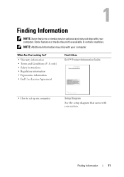
Finding Information 11 only) • Safety instructions • Regulatory information • Ergonomics information • End User License Agreement Find it Here Dell™ Product Information Guide • How to set up my computer Setup Diagram See the setup diagram that came with your computer. What Are You ...
Finding Information 11 only) • Safety instructions • Regulatory information • Ergonomics information • End User License Agreement Find it Here Dell™ Product Information Guide • How to set up my computer Setup Diagram See the setup diagram that came with your computer. What Are You ...
Owner's Manual
Page 12
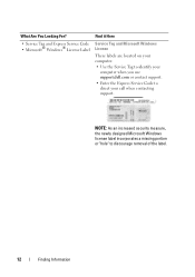
... Tag and Microsoft Windows License These labels are located on your computer. • Use the Service Tag to identify your computer when you use support.dell.com or contact support. • Enter the Express Service Code to discourage removal of the label. 12 Finding Information NOTE: As an increased security measure...
... Tag and Microsoft Windows License These labels are located on your computer. • Use the Service Tag to identify your computer when you use support.dell.com or contact support. • Enter the Express Service Code to discourage removal of the label. 12 Finding Information NOTE: As an increased security measure...
Owner's Manual
Page 13
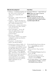
...To download Desktop System Software: you should also reinstall the DSS utility. Online discussion with technical support • Reference - support.dell.com tips, articles from technicians, and online courses, frequently asked questions • Community - DSS provides critical updates for your... operating system and support for your Dell computer. components, such as memory, the hard drive, and the operating system • Customer Care - Certified drivers, patches, ...
...To download Desktop System Software: you should also reinstall the DSS utility. Online discussion with technical support • Reference - support.dell.com tips, articles from technicians, and online courses, frequently asked questions • Community - DSS provides critical updates for your... operating system and support for your Dell computer. components, such as memory, the hard drive, and the operating system • Customer Care - Certified drivers, patches, ...

Owner's Manual
Page 14
What Are You Looking For? • How to use Windows Vista™ • How to work with programs and files • How to personalize my desktop Find it Here Windows Help and Support Center 1 To access Windows Help and Support: • In Windows XP, click Start and click Help and Support. • In Windows Vista™, click the Windows Vista Start button and click Help and Support. 2 Type a word or phrase that describes your problem, and then click the arrow icon. 3 Click the topic that describes your problem. 4 Follow the instructions on the screen. 14 Finding Information
What Are You Looking For? • How to use Windows Vista™ • How to work with programs and files • How to personalize my desktop Find it Here Windows Help and Support Center 1 To access Windows Help and Support: • In Windows XP, click Start and click Help and Support. • In Windows Vista™, click the Windows Vista Start button and click Help and Support. 2 Type a word or phrase that describes your problem, and then click the arrow icon. 3 Click the topic that describes your problem. 4 Follow the instructions on the screen. 14 Finding Information
Owner's Manual
Page 15
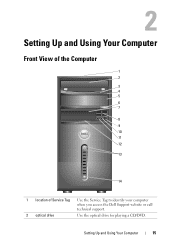
Setting Up and Using Your Computer 15 Setting Up and Using Your Computer Front View of the Computer 1 2 3 4 5 6 7 8 9 10 11 12 13 14 1 location of Service Tag Use the Service Tag to identify your computer when you access the Dell Support website or call technical support. 2 optical drive Use the optical drive for playing a CD/DVD.
Setting Up and Using Your Computer 15 Setting Up and Using Your Computer Front View of the Computer 1 2 3 4 5 6 7 8 9 10 11 12 13 14 1 location of Service Tag Use the Service Tag to identify your computer when you access the Dell Support website or call technical support. 2 optical drive Use the optical drive for playing a CD/DVD.
Owner's Manual
Page 16
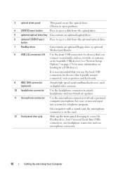
It is on booting to attach a personal computer microphone for devices that you use the back USB connectors for devices that you connect occasionally, such as digital video cameras. 10 headphone connector Use the headphone connector to attach headphones and most kinds of speakers. 11 microphone connector Use the microphone connector to a USB device). button 7 FlexBay drive Can contain an optional floppy drive or optional Media Card Reader. 8 USB 2.0 connectors (4) Use the front USB connectors for voice or musical input into a sound or telephony program. 3 optical drive ...
It is on booting to attach a personal computer microphone for devices that you use the back USB connectors for devices that you connect occasionally, such as digital video cameras. 10 headphone connector Use the headphone connector to attach headphones and most kinds of speakers. 11 microphone connector Use the microphone connector to a USB device). button 7 FlexBay drive Can contain an optional floppy drive or optional Media Card Reader. 8 USB 2.0 connectors (4) Use the front USB connectors for voice or musical input into a sound or telephony program. 3 optical drive ...

Owner's Manual
Page 17
Instead, perform an operating system shutdown. The drive activity light is operating. Setting Up and Using Your Computer 17 The light might also be on when a device such as a CD player is on when the computer reads data from or writes data to turn off the computer. 13 power button, power light 14 drive activity light Press the power button to the hard drive. NOTICE: To avoid losing data, do not use the power button to turn on page 172 for more information. See "Controls and Lights" on the computer. The light in the center of this button indicates power state.
Instead, perform an operating system shutdown. The drive activity light is operating. Setting Up and Using Your Computer 17 The light might also be on when a device such as a CD player is on when the computer reads data from or writes data to turn off the computer. 13 power button, power light 14 drive activity light Press the power button to the hard drive. NOTICE: To avoid losing data, do not use the power button to turn on page 172 for more information. See "Controls and Lights" on the computer. The light in the center of this button indicates power state.
Owner's Manual
Page 18
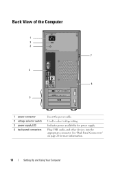
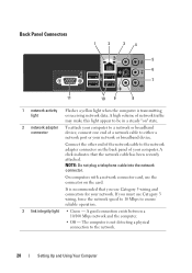
See "Back Panel Connectors" on page 20 for power supply. Plug USB, audio, and other devices into the appropriate connector. Indicates power availability for more information. 18 Setting Up and Using Your Computer Back View of the Computer 1 2 3 7 4 6 5 1 power connector 2 voltage selector switch 3 power supply LED 4 back panel connectors Insert the power cable. Used to select voltage rating.
See "Back Panel Connectors" on page 20 for power supply. Plug USB, audio, and other devices into the appropriate connector. Indicates power availability for more information. 18 Setting Up and Using Your Computer Back View of the Computer 1 2 3 7 4 6 5 1 power connector 2 voltage selector switch 3 power supply LED 4 back panel connectors Insert the power cable. Used to select voltage rating.

Owner's Manual
Page 19
Security cable slot lets you to secure the computer cover to the chassis with the device. 5 card slots 6 padlock rings 7 security cable slot Access connectors for attaching a commercially available theft-deterrent device. Blocking the vents would cause serious thermal problems. Setting Up and Using Your Computer 19 For more information, see the instructions included with a padlock to prevent unauthorized access to the computer. The padlock rings allow you attach a commercially available antitheft device to the inside of the system air vents are for any installed PCI and PCI ...
Security cable slot lets you to secure the computer cover to the chassis with the device. 5 card slots 6 padlock rings 7 security cable slot Access connectors for attaching a commercially available theft-deterrent device. Blocking the vents would cause serious thermal problems. Setting Up and Using Your Computer 19 For more information, see the instructions included with a padlock to prevent unauthorized access to the computer. The padlock rings allow you attach a commercially available antitheft device to the inside of the system air vents are for any installed PCI and PCI ...
Owner's Manual
Page 20
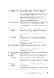
On computers with a network connector card, use Category 3 wiring, force the network speed to 10 Mbps to the network. 20 Setting Up and Using Your Computer A click indicates that you must use the connector on the back panel of the network cable to either a network port or your computer. The computer is not detecting a physical connection to ensure reliable operation. 3 link integrity light • Green - If you use Category 5 wiring and connectors for your network. NOTE: Do not plug a telephone cable into the network connector. It is transmitting or receiving network ...
On computers with a network connector card, use Category 3 wiring, force the network speed to 10 Mbps to the network. 20 Setting Up and Using Your Computer A click indicates that you must use the connector on the back panel of the network cable to either a network port or your computer. The computer is not detecting a physical connection to ensure reliable operation. 3 link integrity light • Green - If you use Category 5 wiring and connectors for your network. NOTE: Do not plug a telephone cable into the network connector. It is transmitting or receiving network ...
Owner's Manual
Page 21
LFE audio channel is found in connector to provide enhanced surround connector audio for voice or musical input into a sound or telephony program On computers with a sound card, the microphone connector is on the card. 8 side L/R surround Use the gray connector to attach a record/playback device such as a cassette player, CD player, or VCR. On computers with a sound card, use the connector on the card. 6 front L/R line-out Use the green line-out connector (available on computers connector with integrated sound) to the main speakers in the surround sound setup. 5 line-in ...
LFE audio channel is found in connector to provide enhanced surround connector audio for voice or musical input into a sound or telephony program On computers with a sound card, the microphone connector is on the card. 8 side L/R surround Use the gray connector to attach a record/playback device such as a cassette player, CD player, or VCR. On computers with a sound card, use the connector on the card. 6 front L/R line-out Use the green line-out connector (available on computers connector with integrated sound) to the main speakers in the surround sound setup. 5 line-in ...
Owner's Manual
Page 22
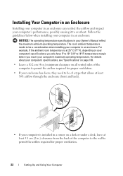
For details about your computer's specifications, see "Specifications" on page 169. • Leave a 10.2 cm (4 in.) minimum clearance on your computer's specifications, you only have 5° to 10° C (9° to 18° F) temperature margin before you reach your computer's performance, possibly causing it to overheat. Follow the guidelines below when installing your computer in an enclosure: NOTICE: The operating temperature specifications in your computer is at least 5.1 cm (2 in.) clearance from the back of the computer to the wall to be a consideration when installing your...
For details about your computer's specifications, see "Specifications" on page 169. • Leave a 10.2 cm (4 in.) minimum clearance on your computer's specifications, you only have 5° to 10° C (9° to 18° F) temperature margin before you reach your computer's performance, possibly causing it to overheat. Follow the guidelines below when installing your computer in an enclosure: NOTICE: The operating temperature specifications in your computer is at least 5.1 cm (2 in.) clearance from the back of the computer to the wall to be a consideration when installing your...
