Owner's Manual
Page 3
... Front Bezel...9 Removing the Expansion Card...9 Installing the Expansion Card...10 Removing the System Fan...10 Installing the System Fan...11 Removing the Memory...12 Installing the Memory...12 Removing the Optical Drive...12 Installing the Optical Drive...13 Removing the Hard Drive...14 Installing the Hard Drive...15 Removing the Wireless...
... Front Bezel...9 Removing the Expansion Card...9 Installing the Expansion Card...10 Removing the System Fan...10 Installing the System Fan...11 Removing the Memory...12 Installing the Memory...12 Removing the Optical Drive...12 Installing the Optical Drive...13 Removing the Hard Drive...14 Installing the Hard Drive...15 Removing the Wireless...
Owner's Manual
Page 12
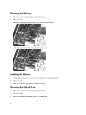
... tabs on each side of the connector on the system board till it snaps into place. 2. Installing the Memory 1. Lift the memory module out of the memory module. 4. Follow the procedures in Before Working Inside Your Computer. 2. Follow the procedures in After Working Inside Your ...Drive 1. Disconnect the data cable and power cable from the optical drive. 12 Remove the cover. 3. Press the memory module into it's connector on the system board. Removing the Memory 1. Remove the cover. 3. Follow the procedures in Before Working Inside Your Computer. 2. Replace the cover. 3....
... tabs on each side of the connector on the system board till it snaps into place. 2. Installing the Memory 1. Lift the memory module out of the memory module. 4. Follow the procedures in Before Working Inside Your Computer. 2. Follow the procedures in After Working Inside Your ...Drive 1. Disconnect the data cable and power cable from the optical drive. 12 Remove the cover. 3. Press the memory module into it's connector on the system board. Removing the Memory 1. Remove the cover. 3. Follow the procedures in Before Working Inside Your Computer. 2. Replace the cover. 3....

Owner's Manual
Page 24
Place the coin-cell battery in it snaps into the socket till it 's socket on the system board. 2. Follow the procedures in Before Working Inside Your Computer. 2. Follow the procedures in After Working Inside Your Computer. Disconnect and un-thread all the cables connected to the system board. 24 Installing the Coin-Cell Battery 1. Remove the: a) cover b) memory c) system fan d) processor e) expansion card f) WLAN card 3. Press the coin-cell battery into place. 3. Removing the System Board 1. Replace the cover. 4. 4. Lift the coin-cell battery out of the computer.
Place the coin-cell battery in it snaps into the socket till it 's socket on the system board. 2. Follow the procedures in Before Working Inside Your Computer. 2. Follow the procedures in After Working Inside Your Computer. Disconnect and un-thread all the cables connected to the system board. 24 Installing the Coin-Cell Battery 1. Remove the: a) cover b) memory c) system fan d) processor e) expansion card f) WLAN card 3. Press the coin-cell battery into place. 3. Removing the System Board 1. Replace the cover. 4. 4. Lift the coin-cell battery out of the computer.

Owner's Manual
Page 26
.... Place the system board into the computer and then slide it towards the back of the computer. 2. password reset jumper 5. PCI Express x1 card slot 7. memory module connectors (DIMM 1 and 2) 14. front USB connector 3. audio connector 6. Replace the screws to secure the system board to the system board. 4. 1. system fan connector...
.... Place the system board into the computer and then slide it towards the back of the computer. 2. password reset jumper 5. PCI Express x1 card slot 7. memory module connectors (DIMM 1 and 2) 14. front USB connector 3. audio connector 6. Replace the screws to secure the system board to the system board. 4. 1. system fan connector...

Owner's Manual
Page 27
Follow the procedures in After Working Inside Your Computer. 27 a) memory b) system fan c) WLAN card d) expansion card e) processor f) cover 5.
Follow the procedures in After Working Inside Your Computer. 27 a) memory b) system fan c) WLAN card d) expansion card e) processor f) cover 5.

Owner's Manual
Page 30
...keyboard has initialized. Table 2. Keys Spacebar Navigation Allows you to the previous page till you view the main screen. When the blue DELL logo is recommended that prompts you to save any hardware in the main screen displays a message that you write down list, if applicable.... Jumper Settings To change a user-selectable option such as the user password. • read the current amount of memory or set the type of hard drive installed. Expands or collapses a drop‐down the System Setup screen information for troubleshooting. 30 This...
...keyboard has initialized. Table 2. Keys Spacebar Navigation Allows you to the previous page till you view the main screen. When the blue DELL logo is recommended that prompts you to save any hardware in the main screen displays a message that you write down list, if applicable.... Jumper Settings To change a user-selectable option such as the user password. • read the current amount of memory or set the type of hard drive installed. Expands or collapses a drop‐down the System Setup screen information for troubleshooting. 30 This...

Owner's Manual
Page 32
Build Date System Date System Time Service Tag Asset Tag Processor Information Processor Type L2 Cache Size L3 Cache Size Memory Information Memory Installed Memory Speed Memory Technology Device Information SATA 0 SATA 1 SATA 2 SATA 3 Table 6. Re-sets the time on the computer's internal ... Default: Enabled Enable or disable the CPU XD feature. Default: Enabled Enable or disable the onboard audio controller. Displays the memory speed. Enable or disable the processor power saving report to the operating system. Enable or disable the onboard LAN controller. Default...
Build Date System Date System Time Service Tag Asset Tag Processor Information Processor Type L2 Cache Size L3 Cache Size Memory Information Memory Installed Memory Speed Memory Technology Device Information SATA 0 SATA 1 SATA 2 SATA 3 Table 6. Re-sets the time on the computer's internal ... Default: Enabled Enable or disable the CPU XD feature. Default: Enabled Enable or disable the onboard audio controller. Displays the memory speed. Enable or disable the processor power saving report to the operating system. Enable or disable the onboard LAN controller. Default...
Owner's Manual
Page 42
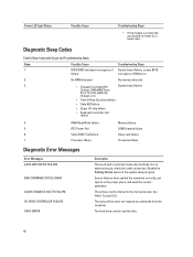
...Clock test failure • Gate A20 failure • Super I/O chip failure • Keyboard controller test failure 4 RAM Read/Write failure Memory failure 5 RTC Power Fail COMS battery failure 6 Video BIOS Test failure Video card failure 7 Processor failure Processor failure Diagnostic Error Messages ...you have spelled the command correctly, put spaces in the proper place, and used the correct pathname. Contact Dell. corruption or ROM error 2 No RAM detected No memory detected 3 • Chipset Error (Intel B75 System board failure Chipset, DMA/IMR/Timer Error for a ...
...Clock test failure • Gate A20 failure • Super I/O chip failure • Keyboard controller test failure 4 RAM Read/Write failure Memory failure 5 RTC Power Fail COMS battery failure 6 Video BIOS Test failure Video card failure 7 Processor failure Processor failure Diagnostic Error Messages ...you have spelled the command correctly, put spaces in the proper place, and used the correct pathname. Contact Dell. corruption or ROM error 2 No RAM detected No memory detected 3 • Chipset Error (Intel B75 System board failure Chipset, DMA/IMR/Timer Error for a ...

Owner's Manual
Page 43
...large to carry out the command. CHARACTERS GATE A20 FAILURE A memory module may be loose. For example, Printer out of memory recorded in non-volatile memory (NVRAM) does not match the memory installed in the Dell Diagnostics. Then, shut down the computer, reinstall the hard drive,...necessary, replace them . Error Messages Description DECREASING AVAILABLE MEMORY One or more memory modules may be faulty or improperly seated. Run the hard drive tests in the hard drive bay. Install a hard drive in the Dell Diagnostics. HARD-DISK DRIVE CONFIGURATION ERROR The computer ...
...large to carry out the command. CHARACTERS GATE A20 FAILURE A memory module may be loose. For example, Printer out of memory recorded in non-volatile memory (NVRAM) does not match the memory installed in the Dell Diagnostics. Then, shut down the computer, reinstall the hard drive,...necessary, replace them . Error Messages Description DECREASING AVAILABLE MEMORY One or more memory modules may be faulty or improperly seated. Run the hard drive tests in the hard drive bay. Install a hard drive in the Dell Diagnostics. HARD-DISK DRIVE CONFIGURATION ERROR The computer ...

Owner's Manual
Page 44
... hardware configuration. The message is most likely to occur after a memory module is trying to boot to non-bootable media, such as a floppy disk or optical drive. Correct the appropriate options in the Dell Diagnostics. For external keyboards, check the cable connection. Restart the ...READ VALUE EXPECTING VALUE MEMORY ALLOCATION ERROR MEMORY DOUBLE WORD LOGIC FAILURE AT ADDRESS, READ VALUE EXPECTING VALUE Description drive. Run the Hard Disk Drive tests in the Dell Diagnostics. The hard drive may be defective. Run the Keyboard Controller test in the Dell Diagnostics. For external ...
... hardware configuration. The message is most likely to occur after a memory module is trying to boot to non-bootable media, such as a floppy disk or optical drive. Correct the appropriate options in the Dell Diagnostics. For external keyboards, check the cable connection. Restart the ...READ VALUE EXPECTING VALUE MEMORY ALLOCATION ERROR MEMORY DOUBLE WORD LOGIC FAILURE AT ADDRESS, READ VALUE EXPECTING VALUE Description drive. Run the Hard Disk Drive tests in the Dell Diagnostics. The hard drive may be defective. Run the Keyboard Controller test in the Dell Diagnostics. For external ...

Owner's Manual
Page 45
..., back up the data (if possible), and then reformat the hard drive. Run the System Set tests in the contact Dell . Reinstall the memory modules and, if necessary, replace them . NO BOOT SECTOR ON HARD DRIVE The operating system may be malfunctioning. NOT ENOUGH...DAY CLOCK STOPPED The reserve battery that you want to charge the battery. If the problem persists, contact Dell. Error Messages Description MEMORY ODD/EVEN LOGIC FAILURE AT ADDRESS, READ A memory module may be malfunctioning. Run the System Set tests in the system setup program does PROGRAM not match the...
..., back up the data (if possible), and then reformat the hard drive. Run the System Set tests in the contact Dell . Reinstall the memory modules and, if necessary, replace them . NO BOOT SECTOR ON HARD DRIVE The operating system may be malfunctioning. NOT ENOUGH...DAY CLOCK STOPPED The reserve battery that you want to charge the battery. If the problem persists, contact Dell. Error Messages Description MEMORY ODD/EVEN LOGIC FAILURE AT ADDRESS, READ A memory module may be malfunctioning. Run the System Set tests in the system setup program does PROGRAM not match the...

Owner's Manual
Page 46
...! CPU fan has failed System fan has failed Possible hard disk drive failure during POST Keyboard failure or loose cable. Run the System Memory tests and the Keyboard Controller test in resolving this problem, consecutive times for it to complete the boot routine three at checkpoint [nnnn].... Error Messages UNEXPECTED INTERRUPT IN PROTECTED MODE X:\ IS NOT ACCESSIBLE. If reseating the cable does not solve the problem, replace the keyboard. Dell recommends that you back up your boot device, ensure that the cables are connected and that the drive is running out of range may ...
...! CPU fan has failed System fan has failed Possible hard disk drive failure during POST Keyboard failure or loose cable. Run the System Memory tests and the Keyboard Controller test in resolving this problem, consecutive times for it to complete the boot routine three at checkpoint [nnnn].... Error Messages UNEXPECTED INTERRUPT IN PROTECTED MODE X:\ IS NOT ACCESSIBLE. If reseating the cable does not solve the problem, replace the keyboard. Dell recommends that you back up your boot device, ensure that the cables are connected and that the drive is running out of range may ...

Owner's Manual
Page 47
...8226; Intel Core i5 series • Intel Pentium Dual-Core • Intel Celeron L2 cache up to 6 MB (depending on the processor) Memory Memory module connector Memory module capacity Type Minimum memory Maximum memory two DIMM slots 2 GB, 4 GB, 6 GB or 8 GB 1333 MHz and 1600 MHz DDR3 (Non-ECC) 2 GB 8 GB ... HD Graphics (with your computer, click Start → Help and Support and select the option to 1.7 GB shared video memory (Microsoft Windows Vista and Windows 7) Audio Integrated Conexant (CX20641-11Z) Network Integrated Realtek 10/100/1000 Mbps Ethernet 47 For more information...
...8226; Intel Core i5 series • Intel Pentium Dual-Core • Intel Celeron L2 cache up to 6 MB (depending on the processor) Memory Memory module connector Memory module capacity Type Minimum memory Maximum memory two DIMM slots 2 GB, 4 GB, 6 GB or 8 GB 1333 MHz and 1600 MHz DDR3 (Non-ECC) 2 GB 8 GB ... HD Graphics (with your computer, click Start → Help and Support and select the option to 1.7 GB shared video memory (Microsoft Windows Vista and Windows 7) Audio Integrated Conexant (CX20641-11Z) Network Integrated Realtek 10/100/1000 Mbps Ethernet 47 For more information...


