User Manual
Page 1
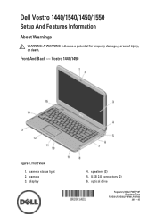
Vostro 1440/1450 Figure 1. camera 3. Front View 1. camera status light 2. optical drive Regulatory Model P22G,P18F Regulatory Type P22G001,P22G003,P18F001,P18F002 2011 - 05 display 4. speakers (2) 5. Dell Vostro 1440/1540/1450/1550 Setup And Features Information About Warnings WARNING: A WARNING indicates a potential for property damage, personal injury, or death. USB 2.0 connectors (2) 6. Front And Back -
Vostro 1440/1450 Figure 1. camera 3. Front View 1. camera status light 2. optical drive Regulatory Model P22G,P18F Regulatory Type P22G001,P22G003,P18F001,P18F002 2011 - 05 display 4. speakers (2) 5. Dell Vostro 1440/1540/1450/1550 Setup And Features Information About Warnings WARNING: A WARNING indicates a potential for property damage, personal injury, or death. USB 2.0 connectors (2) 6. Front And Back -
User Manual
Page 3
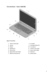
Front And Back - speakers (2) 5. Vostro 1540/1550 Figure 3. keyboard 14. optical drive 6. memory card reader 12. power button 3 camera status light 2. camera 3. USB 2.0 connectors (2) 8. microphone 11. device status lights 13. Front View 1. display 4. optical drive eject button 7. touchpad buttons (2) 10. touchpad 9.
Front And Back - speakers (2) 5. Vostro 1540/1550 Figure 3. keyboard 14. optical drive 6. memory card reader 12. power button 3 camera status light 2. camera 3. USB 2.0 connectors (2) 8. microphone 11. device status lights 13. Front View 1. display 4. optical drive eject button 7. touchpad buttons (2) 10. touchpad 9.
Owners Manual
Page 4
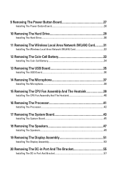
... 40 16 Removing The Processor 41 Installing The Processor 42 17 Removing The System Board 43 Installing The System Board 45 18 Removing The Speakers 47 Installing The Speakers 49 19 Removing The Display Assembly 51 Installing The Display Assembly 53 20 Removing The DC-in Port And The Bracket 55 Installing...
... 40 16 Removing The Processor 41 Installing The Processor 42 17 Removing The System Board 43 Installing The System Board 45 18 Removing The Speakers 47 Installing The Speakers 49 19 Removing The Display Assembly 51 Installing The Display Assembly 53 20 Removing The DC-in Port And The Bracket 55 Installing...
Owners Manual
Page 43
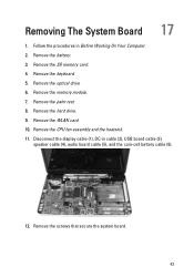
Follow the procedures in cable (2), USB board cable (3), speaker cable (4), audio board cable (5), and the coin-cell battery cable (6). 12. Remove the optical drive. 6. Remove the keyboard. 5. Remove the memory module. 7. Remove the WLAN card. 10. Remove the SD memory card. 4. Remove the hard drive. 9. Removing The System Board 17 1. Remove the palm rest. 8. Remove the battery. 3. Remove the screws that secure the system board. 43 Disconnect the display cable (1), DC-in Before Working On Your Computer. 2. Remove the CPU fan assembly and the heatsink. 11.
Follow the procedures in cable (2), USB board cable (3), speaker cable (4), audio board cable (5), and the coin-cell battery cable (6). 12. Remove the optical drive. 6. Remove the keyboard. 5. Remove the memory module. 7. Remove the WLAN card. 10. Remove the SD memory card. 4. Remove the hard drive. 9. Removing The System Board 17 1. Remove the palm rest. 8. Remove the battery. 3. Remove the screws that secure the system board. 43 Disconnect the display cable (1), DC-in Before Working On Your Computer. 2. Remove the CPU fan assembly and the heatsink. 11.
Owners Manual
Page 45
... USB connectors into their respective sockets and align the system board in cable, USB board cable, audio board cable, coin-cell battery cable, and the speaker cable. 4. Install the palm rest. 9. Install the optical drive. 11. Installing The System Board 1. Install the keyboard. 12. Connect the LCD cable, DC-in place...
... USB connectors into their respective sockets and align the system board in cable, USB board cable, audio board cable, coin-cell battery cable, and the speaker cable. 4. Install the palm rest. 9. Install the optical drive. 11. Installing The System Board 1. Install the keyboard. 12. Connect the LCD cable, DC-in place...
Owners Manual
Page 47
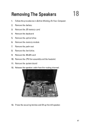
Remove the memory module. 7. Remove the CPU fan assembly and the heatsink. 11. Remove the SD memory card. 4. Release the speaker cable from the routing channel. 18 13. Remove the battery. 3. Remove the palm rest. 8. Press the securing latches and lift up the left speaker. 47 Removing The Speakers 1. Follow the procedures in Before Working On Your Computer. 2. Remove the keyboard. 5. Remove the hard drive. 9. Remove the system board. 12. Remove the optical drive. 6. Remove the WLAN card. 10.
Remove the memory module. 7. Remove the CPU fan assembly and the heatsink. 11. Remove the SD memory card. 4. Release the speaker cable from the routing channel. 18 13. Remove the battery. 3. Remove the palm rest. 8. Press the securing latches and lift up the left speaker. 47 Removing The Speakers 1. Follow the procedures in Before Working On Your Computer. 2. Remove the keyboard. 5. Remove the hard drive. 9. Remove the system board. 12. Remove the optical drive. 6. Remove the WLAN card. 10.
Owners Manual
Page 48
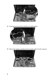
14. Press the securing latches and lift up the right speaker. 15. Remove the speaker assembly and the speaker cable from the computer. 48
14. Press the securing latches and lift up the right speaker. 15. Remove the speaker assembly and the speaker cable from the computer. 48
Owners Manual
Page 49
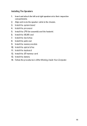
Insert and attach the left and right speakers into their respective compartments. 2. Align and route the speaker cable to the chassis. 3. Install the WLAN card. 7. Install the battery. 14. Install the processor. 5. Install the optical drive. 11. Install the SD memory card. 13. Follow the procedures in After Working Inside Your Computer. 49 Install the hard drive. 8. Install the memory module. 10. Install the palm rest. 9. Install the system board. 4. Install the CPU fan assembly and the heatsink . 6. Installing The Speakers 1. Install the keyboard. 12.
Insert and attach the left and right speakers into their respective compartments. 2. Align and route the speaker cable to the chassis. 3. Install the WLAN card. 7. Install the battery. 14. Install the processor. 5. Install the optical drive. 11. Install the SD memory card. 13. Follow the procedures in After Working Inside Your Computer. 49 Install the hard drive. 8. Install the memory module. 10. Install the palm rest. 9. Install the system board. 4. Install the CPU fan assembly and the heatsink . 6. Installing The Speakers 1. Install the keyboard. 12.
Owners Manual
Page 81
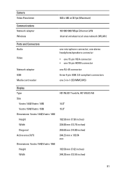
....00 inches) 344.23 mm x 193.54 mm 193.50 mm (7.62 inches) 344.20 mm (13.55 inches) 81 one stereo headphone/speakers connector • one 15-pin VGA connector • one 19-pin HDMI connector one RJ-45 connector three 4-pin USB 2.0-compliant connectors one microphone...area network (WLAN) Ports and Connectors Audio Video Network adapter USB Media card reader one 3-in-1 (SD/MMC/MS) Display Type Size Vostro 1440/Vostro 1450 Vostro 1540/Vostro 1550 Dimensions: Vostro 1440/Vostro 1450 Height Width Diagonal Active area (X/Y) Dimensions: Vostro 1540/Vostro 1550 Height Width HD WLED TrueLife;
....00 inches) 344.23 mm x 193.54 mm 193.50 mm (7.62 inches) 344.20 mm (13.55 inches) 81 one stereo headphone/speakers connector • one 15-pin VGA connector • one 19-pin HDMI connector one RJ-45 connector three 4-pin USB 2.0-compliant connectors one microphone...area network (WLAN) Ports and Connectors Audio Video Network adapter USB Media card reader one 3-in-1 (SD/MMC/MS) Display Type Size Vostro 1440/Vostro 1450 Vostro 1540/Vostro 1550 Dimensions: Vostro 1440/Vostro 1450 Height Width Diagonal Active area (X/Y) Dimensions: Vostro 1540/Vostro 1550 Height Width HD WLED TrueLife;


