User Manual
Page 2
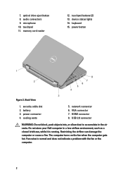
...Fan noise is running. 7. security cable slot 2. Back View 1. Restricting the airflow can damage the computer or cause a fire. device status lights 14. battery 3. power button Figure 2. network connector 6. USB 2.0 connector WARNING: Do not block, push objects into, or allow dust to accumulate in a low-airflow...a closed briefcase, while it is normal and does not indicate a problem with the fan or the computer. 2 Do not store your Dell computer in the air vents. memory card reader 12. keyboard 15. power connector 4. touchpad buttons (2) 13. The computer turns on the ...
...Fan noise is running. 7. security cable slot 2. Back View 1. Restricting the airflow can damage the computer or cause a fire. device status lights 14. battery 3. power button Figure 2. network connector 6. USB 2.0 connector WARNING: Do not block, push objects into, or allow dust to accumulate in a low-airflow...a closed briefcase, while it is normal and does not indicate a problem with the fan or the computer. 2 Do not store your Dell computer in the air vents. memory card reader 12. keyboard 15. power connector 4. touchpad buttons (2) 13. The computer turns on the ...
User Manual
Page 4
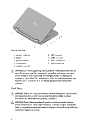
...is normal and does not indicate a problem with electrical outlets worldwide. HDMI connector 8. For additional best practices information, see www.dell.com/regulatory_compliance. power connector 4. network connector 6. The computer turns on the fan when the computer gets hot. audio connectors WARNING:... outlet may cause fire or equipment damage. 4 However, power connectors and power strips vary among countries. battery 3. Do not store your Dell computer in this section, read the safety information that shipped with your computer. Fan noise is running. WARNING...
...is normal and does not indicate a problem with electrical outlets worldwide. HDMI connector 8. For additional best practices information, see www.dell.com/regulatory_compliance. power connector 4. network connector 6. The computer turns on the fan when the computer gets hot. audio connectors WARNING:... outlet may cause fire or equipment damage. 4 However, power connectors and power strips vary among countries. battery 3. Do not store your Dell computer in this section, read the safety information that shipped with your computer. Fan noise is running. WARNING...
User Manual
Page 7
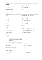
... memory Maximum memory 1 GB / 2 GB / 4 GB DDR3, 1333 MHz 1 GB 8 GB Battery Type Dimensions: Depth Height Width Weight Voltage Temperature range: Operating Non-operating Coin-cell battery 6-cell lithium ion (2.20 Whr) 53.39 mm (2.10 inches) 20.44 mm (0.80 inch) ...to 65 °C (-40 °F to 149 °F) 3 V CR2032 lithium ion AC Adapter Type: Vostro 1440 / Vostro 1450 / Vostro 1540 / Vostro 1550 with integrated video card Vostro 1440 with discrete video card Vostro 1450 with discrete video card Input voltage Input current (maximum) Input frequency Output current: 65 W 65 W 65 W...
... memory Maximum memory 1 GB / 2 GB / 4 GB DDR3, 1333 MHz 1 GB 8 GB Battery Type Dimensions: Depth Height Width Weight Voltage Temperature range: Operating Non-operating Coin-cell battery 6-cell lithium ion (2.20 Whr) 53.39 mm (2.10 inches) 20.44 mm (0.80 inch) ...to 65 °C (-40 °F to 149 °F) 3 V CR2032 lithium ion AC Adapter Type: Vostro 1440 / Vostro 1450 / Vostro 1540 / Vostro 1550 with integrated video card Vostro 1440 with discrete video card Vostro 1450 with discrete video card Input voltage Input current (maximum) Input frequency Output current: 65 W 65 W 65 W...
Owners Manual
Page 3
... Warnings 2 1 Working on Your Computer 7 Before Working Inside Your Computer 7 Recommended Tools...8 Turning Off Your Computer 9 After Working Inside Your Computer 9 2 Removing The Battery 11 Installing The Battery...11 3 Removing The Secure Digital (SD) Card 13 Installing The Secure Digital (SD) Card 14 4 Removing The Hinge Cover 15 Installing The Hinge Cover...
... Warnings 2 1 Working on Your Computer 7 Before Working Inside Your Computer 7 Recommended Tools...8 Turning Off Your Computer 9 After Working Inside Your Computer 9 2 Removing The Battery 11 Installing The Battery...11 3 Removing The Secure Digital (SD) Card 13 Installing The Secure Digital (SD) Card 14 4 Removing The Hinge Cover 15 Installing The Hinge Cover...
Owners Manual
Page 4
... The Wireless Local Area Network (WLAN) Card...........31 Installing The Wireless Local Area Network (WLAN) Card 32 12 Removing The Coin-Cell Battery 33 Installing The Coin-Cell Battery 34 13 Removing The USB Board 35 Installing The USB Board 36 14 Removing The Microphone 37 Installing The Microphone 38 15 Removing...
... The Wireless Local Area Network (WLAN) Card...........31 Installing The Wireless Local Area Network (WLAN) Card 32 12 Removing The Coin-Cell Battery 33 Installing The Coin-Cell Battery 34 13 Removing The USB Board 35 Installing The USB Board 36 14 Removing The Microphone 37 Installing The Microphone 38 15 Removing...
Owners Manual
Page 8
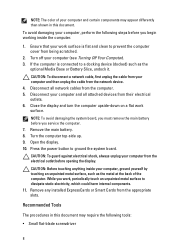
To avoid damaging your computer, ground yourself by touching an unpainted metal surface, such as the optional Media Base or Battery Slice, undock it. CAUTION: To disconnect a network cable, first unplug the cable from your computer (see Turning Off Your ... the electrical outlet before you begin working inside your computer, perform the following tools: • Small flat-blade screwdriver 8 Remove the main battery. 8. CAUTION: To guard against electrical shock, always unplug your computer from their electrical outlets. 6. Disconnect your computer and certain components may...
To avoid damaging your computer, ground yourself by touching an unpainted metal surface, such as the optional Media Base or Battery Slice, undock it. CAUTION: To disconnect a network cable, first unplug the cable from your computer (see Turning Off Your ... the electrical outlet before you begin working inside your computer, perform the following tools: • Small flat-blade screwdriver 8 Remove the main battery. 8. CAUTION: To guard against electrical shock, always unplug your computer from their electrical outlets. 6. Disconnect your computer and certain components may...
Owners Manual
Page 9
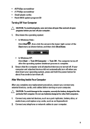
... complete. 2. Ensure that the computer and all open programs before turning on your computer. 9 Connect any external devices, such as a port replicator, battery slice, or media base, and replace any external devices, cards, and cables before you connect any cards, such as shown below, and then click...ensure you turn them off. CAUTION: To avoid damage to your computer. Connect any telephone or network cables to the computer, use batteries designed for this particular Dell computer. Do not use only the battery designed for other Dell computers. 1. The computer turns off .
... complete. 2. Ensure that the computer and all open programs before turning on your computer. 9 Connect any external devices, such as a port replicator, battery slice, or media base, and replace any external devices, cards, and cables before you connect any cards, such as shown below, and then click...ensure you turn them off. CAUTION: To avoid damage to your computer. Connect any telephone or network cables to the computer, use batteries designed for this particular Dell computer. Do not use only the battery designed for other Dell computers. 1. The computer turns off .
Owners Manual
Page 10
Replace the battery. 4. CAUTION: To connect a network cable, first plug the cable into the network device and then plug it into the computer. 3. Connect your computer. 10 Turn on your computer and all attached devices to their electrical outlets. 5.
Replace the battery. 4. CAUTION: To connect a network cable, first plug the cable into the network device and then plug it into the computer. 3. Connect your computer. 10 Turn on your computer and all attached devices to their electrical outlets. 5.
Owners Manual
Page 11
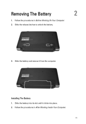
Installing The Battery 1. Removing The Battery 2 1. Slide the battery into its slot until it from the computer. Follow the procedures in Before Working On Your Computer. 2. Slide the release latches to unlock the battery. 3. Slide the battery and remove it clicks into place. 2. Follow the procedures in After Working Inside Your Computer. 11
Installing The Battery 1. Removing The Battery 2 1. Slide the battery into its slot until it from the computer. Follow the procedures in Before Working On Your Computer. 2. Slide the release latches to unlock the battery. 3. Slide the battery and remove it clicks into place. 2. Follow the procedures in After Working Inside Your Computer. 11
Owners Manual
Page 15
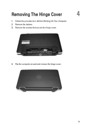
Removing The Hinge Cover 4 1. Remove the screws that secure the hinge cover. 4. Remove the battery. 3. Flip the computer around and remove the hinge cover. 15 Follow the procedures in Before Working On Your Computer. 2.
Removing The Hinge Cover 4 1. Remove the screws that secure the hinge cover. 4. Remove the battery. 3. Flip the computer around and remove the hinge cover. 15 Follow the procedures in Before Working On Your Computer. 2.

Owners Manual
Page 16
Install the battery. 4. Follow the procedures in After Working Inside Your Computer. 16 Installing The Hinge Cover 1. Flip the computer around and install the screws that secure the hinge cover. 3. Install the hinge cover and press on it to secure its connection to the computer. 2.
Install the battery. 4. Follow the procedures in After Working Inside Your Computer. 16 Installing The Hinge Cover 1. Flip the computer around and install the screws that secure the hinge cover. 3. Install the hinge cover and press on it to secure its connection to the computer. 2.
Owners Manual
Page 17
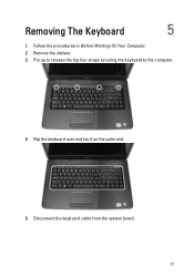
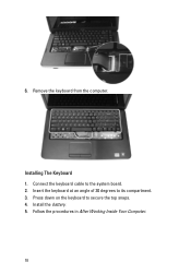
Removing The Keyboard 5 1. Pry up to release the top four snaps securing the keyboard to the computer. 4. Follow the procedures in Before Working On Your Computer. 2. Flip the keyboard over and lay it on the palm rest. 5. Remove the battery. 3. Disconnect the keyboard cable from the system board. 17
Removing The Keyboard 5 1. Pry up to release the top four snaps securing the keyboard to the computer. 4. Follow the procedures in Before Working On Your Computer. 2. Flip the keyboard over and lay it on the palm rest. 5. Remove the battery. 3. Disconnect the keyboard cable from the system board. 17
Owners Manual
Page 18
Follow the procedures in After Working Inside Your Computer. 18 Insert the keyboard at an angle of 30 degrees to secure the top snaps. 4. 6. Remove the keyboard from the computer. Press down on the keyboard to its compartment. 3. Connect the keyboard cable to the system board. 2. Installing The Keyboard 1. Install the battery. 5.
Follow the procedures in After Working Inside Your Computer. 18 Insert the keyboard at an angle of 30 degrees to secure the top snaps. 4. 6. Remove the keyboard from the computer. Press down on the keyboard to its compartment. 3. Connect the keyboard cable to the system board. 2. Installing The Keyboard 1. Install the battery. 5.
Owners Manual
Page 19
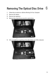
Remove the battery. 3. Remove the screw that secures the optical drive. 5. Remove the keyboard. 4. Use a screwdriver to gently pry the optical drive out of the computer. 19 Follow the procedures in Before Working On Your Computer. 2. Removing The Optical Disc Drive 6 1.
Remove the battery. 3. Remove the screw that secures the optical drive. 5. Remove the keyboard. 4. Use a screwdriver to gently pry the optical drive out of the computer. 19 Follow the procedures in Before Working On Your Computer. 2. Removing The Optical Disc Drive 6 1.

Owners Manual
Page 20
Install the battery. 5. Installing The Optical Disc Drive 1. Slide the optical drive into the compartment on the left side of the chassis. 2. Install the keyboard. 4. Follow the procedures in After Working Inside Your Computer. 20 Tighten the screw to secure the optical drive to the computer. 3.
Install the battery. 5. Installing The Optical Disc Drive 1. Slide the optical drive into the compartment on the left side of the chassis. 2. Install the keyboard. 4. Follow the procedures in After Working Inside Your Computer. 20 Tighten the screw to secure the optical drive to the computer. 3.
Owners Manual
Page 21
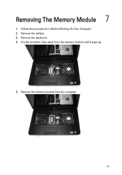
Remove the battery. 3. Remove the memory module from the memory module until it pops up. 5. Follow the procedures in Before Working On Your Computer. 2. Removing The Memory Module 7 1. Remove the keyboard. 4. Pry the retention clips away from the computer. 21
Remove the battery. 3. Remove the memory module from the memory module until it pops up. 5. Follow the procedures in Before Working On Your Computer. 2. Removing The Memory Module 7 1. Remove the keyboard. 4. Pry the retention clips away from the computer. 21

Owners Manual
Page 22
Press down on the memory module until the retention clips secure the memory module in After Working Inside Your Computer. 22 Follow the procedures in place. 3. Install the keyboard. 4. Install the battery. 5. Insert the memory module into the memory socket. 2. Installing The Memory Module 1.
Press down on the memory module until the retention clips secure the memory module in After Working Inside Your Computer. 22 Follow the procedures in place. 3. Install the keyboard. 4. Install the battery. 5. Insert the memory module into the memory socket. 2. Installing The Memory Module 1.
Owners Manual
Page 23
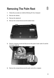
Follow the procedures in Before Working On Your Computer. 2. Remove the battery. 3. Remove the screws that secure the palm rest to the computer. 23 Remove the keyboard. 4. Remove the screws that secure the bottom base. 5. Flip the computer around and disconnect the power board cable (1) and the touchpad cable (2). 6. Removing The Palm Rest 8 1.
Follow the procedures in Before Working On Your Computer. 2. Remove the battery. 3. Remove the screws that secure the palm rest to the computer. 23 Remove the keyboard. 4. Remove the screws that secure the bottom base. 5. Flip the computer around and disconnect the power board cable (1) and the touchpad cable (2). 6. Removing The Palm Rest 8 1.
Owners Manual
Page 25
Insert the palm rest towards the display screen at a 30-degree angle. 2. Install the keyboard. 7. Install the battery. 8. Install the screws that secure the bottom base. 6. Follow the procedures in After Working Inside Your Computer. 25 Installing The Palm Rest 1. Connect the power board cable and touchpad cable to secure all the snaps. 3. Flip the computer around and install the screws that secure the palm rest to the computer. 5. Align and adjust the palm rest into position before pressing it down to their respective connectors. 4.
Insert the palm rest towards the display screen at a 30-degree angle. 2. Install the keyboard. 7. Install the battery. 8. Install the screws that secure the bottom base. 6. Follow the procedures in After Working Inside Your Computer. 25 Installing The Palm Rest 1. Connect the power board cable and touchpad cable to secure all the snaps. 3. Flip the computer around and install the screws that secure the palm rest to the computer. 5. Align and adjust the palm rest into position before pressing it down to their respective connectors. 4.
Owners Manual
Page 27
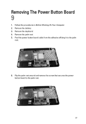
Follow the procedures in Before Working On Your Computer. 2. Remove the palm rest. 5. Remove the keyboard. 4. Remove the battery. 3. Peel the power button board cable from the adhesive affixing it to the palm rest. 27 Flip the palm rest around and remove the screw that secures the power button board to the palm rest. 6. Removing The Power Button Board 9 1.
Follow the procedures in Before Working On Your Computer. 2. Remove the palm rest. 5. Remove the keyboard. 4. Remove the battery. 3. Peel the power button board cable from the adhesive affixing it to the palm rest. 27 Flip the palm rest around and remove the screw that secures the power button board to the palm rest. 6. Removing The Power Button Board 9 1.

