
Owners Manual
Page 3
... Tools...8 Turning Off Your Computer...8 After Working Inside Your Computer 9 2 Removing and Installing Components 10 Removing the Battery...10 Installing the Battery...11 Removing the Optical Drive...11 Installing the Optical Drive...11 Removing the Access Panel...11 Installing the Access Panel...12 Removing the Hard Drive...12 Installing the Hard Drive...13 Removing the Memory Module...13 Installing the Memory Module...14 Removing the WLAN Card...14 Installing the WLAN Card...14 Removing the Keyboard...15 Installing the Keyboard...16 Removing the Palmrest Assembly...17 Installing the...
... Tools...8 Turning Off Your Computer...8 After Working Inside Your Computer 9 2 Removing and Installing Components 10 Removing the Battery...10 Installing the Battery...11 Removing the Optical Drive...11 Installing the Optical Drive...11 Removing the Access Panel...11 Installing the Access Panel...12 Removing the Hard Drive...12 Installing the Hard Drive...13 Removing the Memory Module...13 Installing the Memory Module...14 Removing the WLAN Card...14 Installing the WLAN Card...14 Removing the Keyboard...15 Installing the Keyboard...16 Removing the Palmrest Assembly...17 Installing the...
Owners Manual
Page 4
......32 Removing the Power Connector...32 Installing the Power Connector...33 3 System Setup...34 Boot Sequence...34 Navigation Keys...34 System Setup Options...35 Updating the BIOS ...39 System and Setup Password...39 Assigning a System Password and Setup Password 40 Deleting or Changing an Existing System and/or Setup Password 40 4 Diagnostics...41 Enhanced Pre-Boot System Assessment (ePSA) Diagnostics 41 Device Status Lights...41 Power Status Lights...42 5 Specifications...43 Specifications...43 6 Contacting Dell 48 Contacting Dell...
......32 Removing the Power Connector...32 Installing the Power Connector...33 3 System Setup...34 Boot Sequence...34 Navigation Keys...34 System Setup Options...35 Updating the BIOS ...39 System and Setup Password...39 Assigning a System Password and Setup Password 40 Deleting or Changing an Existing System and/or Setup Password 40 4 Diagnostics...41 Enhanced Pre-Boot System Assessment (ePSA) Diagnostics 41 Device Status Lights...41 Power Status Lights...42 5 Specifications...43 Specifications...43 6 Contacting Dell 48 Contacting Dell...
Owners Manual
Page 7
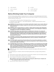
... avoid electrostatic discharge, ground yourself by using a wrist grounding strap or by the online or telephone service and support team. Hold a component such as directed by periodically touching an unpainted metal surface, such as a connector on the locking tabs before connecting to prevent the computer cover from the network device. 4. if you connect a cable, ensure that both connectors are disconnecting this...
... avoid electrostatic discharge, ground yourself by using a wrist grounding strap or by the online or telephone service and support team. Hold a component such as directed by periodically touching an unpainted metal surface, such as a connector on the locking tabs before connecting to prevent the computer cover from the network device. 4. if you connect a cable, ensure that both connectors are disconnecting this...

Owners Manual
Page 8
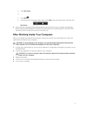
... work surface. b. a. Click the • In Windows 7: and select Shut down . Turn the computer top-side up. 9. Using a touch-enabled device: a. Using a mouse: and then select Shut down . 1. b. Disconnect your computer, ground yourself by touching an unpainted metal surface, such as the metal at the back of the screen and click Settings. NOTE: To avoid damaging the system board, you must remove the main battery...
... work surface. b. a. Click the • In Windows 7: and select Shut down . Turn the computer top-side up. 9. Using a touch-enabled device: a. Using a mouse: and then select Shut down . 1. b. Disconnect your computer, ground yourself by touching an unpainted metal surface, such as the metal at the back of the screen and click Settings. NOTE: To avoid damaging the system board, you must remove the main battery...
Owners Manual
Page 9
Do not use only the battery designed for other Dell computers. 1. CAUTION: To connect a network cable, first plug the cable into the network device and then plug it into the computer. 3. If your computer and attached devices did not automatically turn them off . Connect any external devices, such as a port replicator or media base, and replace any external devices, cards, and cables before turning on your computer. 9 Click Start . 2. Ensure that the computer and...
Do not use only the battery designed for other Dell computers. 1. CAUTION: To connect a network cable, first plug the cable into the network device and then plug it into the computer. 3. If your computer and attached devices did not automatically turn them off . Connect any external devices, such as a port replicator or media base, and replace any external devices, cards, and cables before turning on your computer. 9 Click Start . 2. Ensure that the computer and...

Owners Manual
Page 13
Lift the hard drive upwards from its socket on the system board. 13 battery 4. Remove the memory module from the computer [3]. Installing the Hard Drive 1. Slide the hard drive into the connector. 2. Remove: a. access panel 3. access panel b. Follow the procedures in After Working Inside Your computer. Pry the securing clips away from the memory module until it to the chassis. 3. Removing the Memory Module 1. battery b. Tighten the screw to secure it pops up. 4. Install: a. Follow the procedures in Before Working Inside Your Computer. 2. c.
Lift the hard drive upwards from its socket on the system board. 13 battery 4. Remove the memory module from the computer [3]. Installing the Hard Drive 1. Slide the hard drive into the connector. 2. Remove: a. access panel 3. access panel b. Follow the procedures in After Working Inside Your computer. Pry the securing clips away from the memory module until it to the chassis. 3. Removing the Memory Module 1. battery b. Tighten the screw to secure it pops up. 4. Install: a. Follow the procedures in Before Working Inside Your Computer. 2. c.

Owners Manual
Page 14
.... 4. Install the base cover. 5. Disconnect the WLAN cables from the computer. Place the WLAN card into the socket and press to its connectors [1]. Installing the Memory Module 1. Install the battery. 4. Follow the procedures in After Working Inside Your computer. 14 Follow the procedures in Before Working Inside Your Computer. 2. Perform the following steps to the computer [2]. 4. Installing the WLAN Card 1. Connect the WLAN cables to lock...
.... 4. Install the base cover. 5. Disconnect the WLAN cables from the computer. Place the WLAN card into the socket and press to its connectors [1]. Installing the Memory Module 1. Install the battery. 4. Follow the procedures in After Working Inside Your computer. 14 Follow the procedures in Before Working Inside Your Computer. 2. Perform the following steps to the computer [2]. 4. Installing the WLAN Card 1. Connect the WLAN cables to lock...

Owners Manual
Page 16
... slots. 4. Follow the instructions below in place. 5. NOTE: When a new keyboard is to the connector on a flat and clean surface. 2. Lift the keyboard cable and fold the keyboard-backlight cable at the fold line. 3. Follow the procedures in After Working Inside Your computer. Using the alignment line, fold the keyboard cable. 16 Installing the Keyboard 1. Install the battery. 6. Place the keyboard on the system board. 2. Flip the keyboard after connecting...
... slots. 4. Follow the instructions below in place. 5. NOTE: When a new keyboard is to the connector on a flat and clean surface. 2. Lift the keyboard cable and fold the keyboard-backlight cable at the fold line. 3. Follow the procedures in After Working Inside Your computer. Using the alignment line, fold the keyboard cable. 16 Installing the Keyboard 1. Install the battery. 6. Place the keyboard on the system board. 2. Flip the keyboard after connecting...

Owners Manual
Page 19
...: 19 battery b. access panel d. palmrest assembly 3. Perform the following steps as shown in Before Working Inside Your Computer. 2. Connect the touchpad and power cables to the system board. 4. WLAN e. memory module f. Turn the computer over and tighten the screws at the base of the computer. 5. hard drive d. access panel f. optical disk-drive g. optical disk-drive c. Tighten the screws to secure it clicks in After Working Inside Your computer. battery 6. Removing the Battery Connector 1. hard drive e. Follow...
...: 19 battery b. access panel d. palmrest assembly 3. Perform the following steps as shown in Before Working Inside Your Computer. 2. Connect the touchpad and power cables to the system board. 4. WLAN e. memory module f. Turn the computer over and tighten the screws at the base of the computer. 5. hard drive d. access panel f. optical disk-drive g. optical disk-drive c. Tighten the screws to secure it clicks in After Working Inside Your computer. battery 6. Removing the Battery Connector 1. hard drive e. Follow...

Owners Manual
Page 25
... d. Follow the procedures in the illustration: a. optical disk-drive c. palmrest assembly 3. Disconnect display (eDP) cables [2]. 25 Removing the System Board 1. Remove: a. WLAN f. Follow the procedures in place. 2. access panel d. b. hard drive e. optical disk-drive h. hard drive f. battery b. memory module g. battery 4. WLAN card e. Connect the speakers to lock in Before Working Inside Your Computer. 2. keyboard h. Disconnect speaker and power cable [1]. Installing the Speakers 1. Install: a. Insert the speakers into the chassis and press the...
... d. Follow the procedures in the illustration: a. optical disk-drive c. palmrest assembly 3. Disconnect display (eDP) cables [2]. 25 Removing the System Board 1. Remove: a. WLAN f. Follow the procedures in place. 2. access panel d. b. hard drive e. optical disk-drive h. hard drive f. battery b. memory module g. battery 4. WLAN card e. Connect the speakers to lock in Before Working Inside Your Computer. 2. keyboard h. Disconnect speaker and power cable [1]. Installing the Speakers 1. Install: a. Insert the speakers into the chassis and press the...

Owners Manual
Page 27
...system board. 6. hard drive e. optical disk-drive h. Connect the power connector to the computer. 7. Install: a. memory module f. battery 8. Follow the procedures in After Working Inside Your computer. Place the display panel on a stable surface and lift the bezel from the computer. 27 palmrest assembly b. access panel g. Follow the procedures in Before Working Inside Your Computer. 2. hard drive e. memory module d. Remove: a. 4. battery b. Removing the Display Assembly 1. palmrest assembly h. optical disk-drive c. system board 3. keyboard c. keyboard g.
...system board. 6. hard drive e. optical disk-drive h. Connect the power connector to the computer. 7. Install: a. memory module f. battery 8. Follow the procedures in After Working Inside Your computer. Place the display panel on a stable surface and lift the bezel from the computer. 27 palmrest assembly b. access panel g. Follow the procedures in Before Working Inside Your Computer. 2. hard drive e. memory module d. Remove: a. 4. battery b. Removing the Display Assembly 1. palmrest assembly h. optical disk-drive c. system board 3. keyboard c. keyboard g.

Owners Manual
Page 28
Remove the screws securing the display panel to access the cables underneath. 28 Then, flip the display panel to the display assembly. 5. Remove the screws that secure the display hinges to the display assembly. Then, lift and remove the display hinges away from the display assembly. 6.
Remove the screws securing the display panel to access the cables underneath. 28 Then, flip the display panel to the display assembly. 5. Remove the screws that secure the display hinges to the display assembly. Then, lift and remove the display hinges away from the display assembly. 6.

Owners Manual
Page 31
... in Before Working Inside Your Computer. 2. Disconnect the system fan's cable from the system board [3]. 31 Lift the heatsink from the system board. Insert the camera into the display assembly. 2. display assembly b. palmrest assembly c. hard drive f. WLAN g. Follow the procedures in After Working Inside Your computer. memory module e. battery 4. Remove the screws that secure the heatsink to the system board [1] c. optical disk-drive c. b. Remove: a. hard drive e. Removing the Heatsink 1. keyboard g. access panel h. Connect the camera cable. 3. palmrest...
... in Before Working Inside Your Computer. 2. Disconnect the system fan's cable from the system board [3]. 31 Lift the heatsink from the system board. Insert the camera into the display assembly. 2. display assembly b. palmrest assembly c. hard drive f. WLAN g. Follow the procedures in After Working Inside Your computer. memory module e. battery 4. Remove the screws that secure the heatsink to the system board [1] c. optical disk-drive c. b. Remove: a. hard drive e. Removing the Heatsink 1. keyboard g. access panel h. Connect the camera cable. 3. palmrest...

Owners Manual
Page 32
... procedures in the illustration: a. optical disk-drive c. WLAN g. battery 4. memory module f. Perform the following steps as shown in Before Working Inside Your Computer. 2. Disconnect the power connector from the system board [1]. 32 Connect the system fan's cable to the system board. 2. memory module e. hard drive f. Follow the procedures in After Working Inside Your computer. Remove: a. keyboard g. palmrest assembly c. access panel h. Removing the Power Connector 1. access panel d. Installing the Heatsink Assembly 1. keyboard d. Insert the heatsink and tighten...
... procedures in the illustration: a. optical disk-drive c. WLAN g. battery 4. memory module f. Perform the following steps as shown in Before Working Inside Your Computer. 2. Disconnect the power connector from the system board [1]. 32 Connect the system fan's cable to the system board. 2. memory module e. hard drive f. Follow the procedures in After Working Inside Your computer. Remove: a. keyboard g. palmrest assembly c. access panel h. Removing the Power Connector 1. access panel d. Installing the Heatsink Assembly 1. keyboard d. Insert the heatsink and tighten...
Owners Manual
Page 34
... add or remove hardware • View the system hardware configuration • Enable or disable integrated devices • Set performance and power management thresholds • Manage your computer hardware and specify BIOS‐level options. Navigation Keys The following table displays the system setup navigation keys. NOTE: For most of the system setup options, changes that you to bypass the System Setup‐defined boot device order and boot directly to a specific device (for example: optical drive or hard drive). The boot-menu options are...
... add or remove hardware • View the system hardware configuration • Enable or disable integrated devices • Set performance and power management thresholds • Manage your computer hardware and specify BIOS‐level options. Navigation Keys The following table displays the system setup navigation keys. NOTE: For most of the system setup options, changes that you to bypass the System Setup‐defined boot device order and boot directly to a specific device (for example: optical drive or hard drive). The boot-menu options are...

Owners Manual
Page 37
board network card. Default: Enabled Enables or disables internal Bluetooth. Option Integrated NIC USB Emulation USB Wake Support SATA Operation Adapter Warnings Function Key Behavior Battery Health Miscellaneous Devices External USB Ports Microphone Camera Internal Bluetooth Internal WLAN Media Card Reader Optical Drive Boot Disable USB debug Description Enable or disable the Default: Enabled power supply to wake up the computer from standby. Enable or disable the Default: Enabled USB emulation feature. Default: AHCI Enables or disables adapter warnings. ...
board network card. Default: Enabled Enables or disables internal Bluetooth. Option Integrated NIC USB Emulation USB Wake Support SATA Operation Adapter Warnings Function Key Behavior Battery Health Miscellaneous Devices External USB Ports Microphone Camera Internal Bluetooth Internal WLAN Media Card Reader Optical Drive Boot Disable USB debug Description Enable or disable the Default: Enabled power supply to wake up the computer from standby. Enable or disable the Default: Enabled USB emulation feature. Default: AHCI Enables or disables adapter warnings. ...

Owners Manual
Page 38
... (Default: Not Set) This field displays if a system password is set for this computer or not (Default: Not Set) This field displays if an HDD password is set for this computer or not (Default: Not Set) Allows you to change the boot sequence. The Boot tab allows you to add/remove permission for changing passwords. Boot Options Option Fast Boot Boot List Option File Browser Add Boot Option File Browser Del Boot Option Secure Boot Load Legacy Option ROM Boot Option Priorities Boot Option #1 Boot Option #2 Boot Option #3 Description Enable or disable fast boot...
... (Default: Not Set) This field displays if a system password is set for this computer or not (Default: Not Set) This field displays if an HDD password is set for this computer or not (Default: Not Set) Allows you to change the boot sequence. The Boot tab allows you to add/remove permission for changing passwords. Boot Options Option Fast Boot Boot List Option File Browser Add Boot Option File Browser Del Boot Option Secure Boot Load Legacy Option ROM Boot Option Priorities Boot Option #1 Boot Option #2 Boot Option #3 Description Enable or disable fast boot...
Owners Manual
Page 39
... Setup Password You can also analyze which drivers need an update. CAUTION: Anyone can access the data stored on the screen. This section allows you must enter to access and make changes to save the file on to save , discard, and load default settings before exiting from the list. 6. Click Get drivers and click View All Drivers. Click Run to dell.com/support. 3. If you cannot find the Service...
... Setup Password You can also analyze which drivers need an update. CAUTION: Anyone can access the data stored on the screen. This section allows you must enter to access and make changes to save the file on to save , discard, and load default settings before exiting from the list. 6. Click Get drivers and click View All Drivers. Click Run to dell.com/support. 3. If you cannot find the Service...
Owners Manual
Page 41
... Pre-boot System Assessment window is displayed, listing all the detected devices. 4. If you turn on a specific device, press and click Yes to stop the diagnostic test. 5. Select the device from the left pane and click Run Tests. 6. Note the error code and contact Dell. As the computer boots, press the key as system diagnostics) performs a complete check of problems encountered during testing CAUTION: Use the...
... Pre-boot System Assessment window is displayed, listing all the detected devices. 4. If you turn on a specific device, press and click Yes to stop the diagnostic test. 5. Select the device from the left pane and click Run Tests. 6. Note the error code and contact Dell. As the computer boots, press the key as system diagnostics) performs a complete check of problems encountered during testing CAUTION: Use the...

Owners Manual
Page 44
...° Description 10/100/1000 Mbps Ethernet LAN on Motherboard (LOM) • Wi-Fi 802.11 b/g/n • Bluetooth 4.0 Description one headphone/microphone combo port (headset) VGA one RJ-45 port • one USB 3.0 port Audio Feature Type Controller Stereo conversion Interface Speakers Volume controls Table 10. Camera Feature Camera Resolution Video Resolution (maximum) Diagonal viewing angle Table 12. Table 9. Video Feature Video type Video Controller: UMA Discrete Data bus: External display support Table 11.
...° Description 10/100/1000 Mbps Ethernet LAN on Motherboard (LOM) • Wi-Fi 802.11 b/g/n • Bluetooth 4.0 Description one headphone/microphone combo port (headset) VGA one RJ-45 port • one USB 3.0 port Audio Feature Type Controller Stereo conversion Interface Speakers Volume controls Table 10. Camera Feature Camera Resolution Video Resolution (maximum) Diagonal viewing angle Table 12. Table 9. Video Feature Video type Video Controller: UMA Discrete Data bus: External display support Table 11.


