Dell Vostro 153558 Owners Manual
Page 3
...5 Recommended Tools...6 Turning Off Your Computer...6 After Working Inside Your Computer 7 2 Removing and Installing Components 8 Removing the Battery...8 Installing the Battery...9 Removing the Optical-disk Drive...9 Installing the Optical-disk Drive...9 Removing the Access Panel...9 Installing the Access Panel...10 Removing... Card...13 Installing the WLAN Card...13 Removing the Coin-Cell Battery...13 Installing the Coin-cell battery...14 Removing the Keyboard...14 Installing the Keyboard...15 Removing the Base Cover...15 Installing the Base Cover...17 Removing the Input/Output (I/O) Board ...
...5 Recommended Tools...6 Turning Off Your Computer...6 After Working Inside Your Computer 7 2 Removing and Installing Components 8 Removing the Battery...8 Installing the Battery...9 Removing the Optical-disk Drive...9 Installing the Optical-disk Drive...9 Removing the Access Panel...9 Installing the Access Panel...10 Removing... Card...13 Installing the WLAN Card...13 Removing the Coin-Cell Battery...13 Installing the Coin-cell battery...14 Removing the Keyboard...14 Installing the Keyboard...15 Removing the Base Cover...15 Installing the Base Cover...17 Removing the Input/Output (I/O) Board ...
Dell Vostro 153558 Owners Manual
Page 6
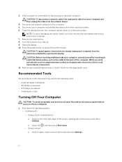
... the network device. 4. Recommended Tools The procedures in from the electrical outlet before you must remove the main battery before opening the Charms menu and select Settings. Using a touch-enabled device: a. Remove the main battery. 8. CAUTION: To guard against electrical shock, always unplug your computer and then unplug the cable from the...
... the network device. 4. Recommended Tools The procedures in from the electrical outlet before you must remove the main battery before opening the Charms menu and select Settings. Using a touch-enabled device: a. Remove the main battery. 8. CAUTION: To guard against electrical shock, always unplug your computer and then unplug the cable from the...

Dell Vostro 153558 Owners Manual
Page 7
... you connect any cards, such as shown below, and then click Shut Down.. 2. Do not use only the battery designed for this particular Dell computer. Click Start . 2. After Working Inside Your Computer After you complete any telephone or network cables to the computer,... use batteries designed for about 4 seconds to their electrical outlets. 5. Connect any replacement procedure, ensure you shut down . 1. b. Connect your operating system, press and hold the power button for other Dell computers. 1. CAUTION: To connect a network cable...
... you connect any cards, such as shown below, and then click Shut Down.. 2. Do not use only the battery designed for this particular Dell computer. Click Start . 2. After Working Inside Your Computer After you complete any telephone or network cables to the computer,... use batteries designed for about 4 seconds to their electrical outlets. 5. Connect any replacement procedure, ensure you shut down . 1. b. Connect your operating system, press and hold the power button for other Dell computers. 1. CAUTION: To connect a network cable...
Dell Vostro 153558 Owners Manual
Page 8
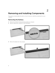
Slide the release latch outwards to remove or install the components from the computer. 8 Remove the battery from your computer. 2 Removing and Installing Components This section provides detailed information on how to unlock the battery. 3. Follow the procedures in Before Working Inside Your Computer. 2. Removing the Battery 1.
Slide the release latch outwards to remove or install the components from the computer. 8 Remove the battery from your computer. 2 Removing and Installing Components This section provides detailed information on how to unlock the battery. 3. Follow the procedures in Before Working Inside Your Computer. 2. Removing the Battery 1.

Dell Vostro 153558 Owners Manual
Page 9
...-disk Drive 1. Perform the following steps as shown in Before Working Inside Your Computer. 2. c. Follow the procedures in the illustration: a. Remove battery. 3. Remove the screws that secures the optical-disk drive (ODD) to the computer [1]. Lift the access panel partially at a 45-degree angle [2].... a. Remove the screw that secure the access panel to secure the ODD. 3. Press on the tab indicated using a scribe [2]. Remove the battery. 3. Follow the procedures in After Working Inside Your computer . b. Slide the ODD out of the computer [3]. Insert the ODD into its ...
...-disk Drive 1. Perform the following steps as shown in Before Working Inside Your Computer. 2. c. Follow the procedures in the illustration: a. Remove battery. 3. Remove the screws that secures the optical-disk drive (ODD) to the computer [1]. Lift the access panel partially at a 45-degree angle [2].... a. Remove the screw that secure the access panel to secure the ODD. 3. Press on the tab indicated using a scribe [2]. Remove the battery. 3. Follow the procedures in After Working Inside Your computer . b. Slide the ODD out of the computer [3]. Insert the ODD into its ...

Dell Vostro 153558 Owners Manual
Page 10
Tighten the screws to secure the access panel to remove it up to the computer. 3. battery b. Disconnect the hard drive cable from the computer. Installing the Access Panel 1. Place the access panel to align with the screw holes at the back...the illustration: a. Perform the following steps as shown in Before Working Inside Your Computer. 2. Follow the procedures in After Working Inside Your computer . Install the battery. 4. Removing the Hard Drive 1. access panel 3. Remove: a. Remove the access panel from the system board and lift it from the computer [1,2]. 10 4.
Tighten the screws to secure the access panel to remove it up to the computer. 3. battery b. Disconnect the hard drive cable from the computer. Installing the Access Panel 1. Place the access panel to align with the screw holes at the back...the illustration: a. Perform the following steps as shown in Before Working Inside Your Computer. 2. Follow the procedures in After Working Inside Your computer . Install the battery. 4. Removing the Hard Drive 1. access panel 3. Remove: a. Remove the access panel from the system board and lift it from the computer [1,2]. 10 4.

Dell Vostro 153558 Owners Manual
Page 12
Tighten the screws that secure the hard drive to the chassis. 5. Removing the Memory Module 1. Tighten the screw to secure it pops up. 4. battery 6. battery b. Follow the procedures in the bracket. 2. access panel 3. access panel b. Installing the Hard Drive 1. Place the hard drive in Before Working Inside Your Computer. 2. Install: a. ...
Tighten the screws that secure the hard drive to the chassis. 5. Removing the Memory Module 1. Tighten the screw to secure it pops up. 4. battery 6. battery b. Follow the procedures in the bracket. 2. access panel 3. access panel b. Installing the Hard Drive 1. Place the hard drive in Before Working Inside Your Computer. 2. Install: a. ...

Dell Vostro 153558 Owners Manual
Page 13
... the WLAN card to the white triangle). 3. access panel 3. Push the coin-cell release latch using a scribe and then pull the coin-cell battery to the system board [3]. Follow the procedures in Before Working Inside Your Computer. 2. Follow the procedures in After Working Inside Your computer . access ...the screw to secure it from its socket [4]. Follow the procedures in Before Working Inside Your Computer. 2. Removing the WLAN Card 1. battery 4. Insert the WLAN card into the socket and press to the system board. 2. Perform the following steps as shown in the illustration: a.
... the WLAN card to the white triangle). 3. access panel 3. Push the coin-cell release latch using a scribe and then pull the coin-cell battery to the system board [3]. Follow the procedures in Before Working Inside Your Computer. 2. Follow the procedures in After Working Inside Your computer . access ...the screw to secure it from its socket [4]. Follow the procedures in Before Working Inside Your Computer. 2. Removing the WLAN Card 1. battery 4. Insert the WLAN card into the socket and press to the system board. 2. Perform the following steps as shown in the illustration: a.

Dell Vostro 153558 Owners Manual
Page 14
Insert the coin-cell battery and press to access the keyboard connector cable underneath [1,2]. 14 access panel b. Follow the procedures in Before Working Inside Your Computer. 2. Follow the procedures in After Working Inside Your computer . Slide and lift the keyboard to lock it. 2. Removing the Keyboard 1. Install: a. Release the keyboard by prying on the keyboard release tabs using a scribe. 4. battery 3. Perform the following steps as shown in the illustration: a. Installing the Coin-cell battery 1. Remove the battery. 3.
Insert the coin-cell battery and press to access the keyboard connector cable underneath [1,2]. 14 access panel b. Follow the procedures in Before Working Inside Your Computer. 2. Follow the procedures in After Working Inside Your computer . Slide and lift the keyboard to lock it. 2. Removing the Keyboard 1. Install: a. Release the keyboard by prying on the keyboard release tabs using a scribe. 4. battery 3. Perform the following steps as shown in the illustration: a. Installing the Coin-cell battery 1. Remove the battery. 3.
Dell Vostro 153558 Owners Manual
Page 15
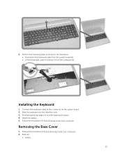
.... 2. Follow the procedures in After Working Inside Your computer . 5. Lift the keyboard cable to lock the keyboard in the illustration: a. Remove: a. Install the battery. 5. Removing the Base Cover 1. battery 15 Press along the top edges to remove it from the system board [1]. b. Connect the keyboard cable to the connector on the system board...
.... 2. Follow the procedures in After Working Inside Your computer . 5. Lift the keyboard cable to lock the keyboard in the illustration: a. Remove: a. Install the battery. 5. Removing the Base Cover 1. battery 15 Press along the top edges to remove it from the system board [1]. b. Connect the keyboard cable to the connector on the system board...
Dell Vostro 153558 Owners Manual
Page 17
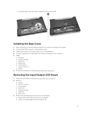
Tighten the screws to secure the base cover to the system board. 3. memory module c. battery 6. Follow the procedures in place. 2. optical-disk drive c. keyboard g. b. Connect the ODD connector to the palmrest. 4. access panel d. Pry up the... base cover and slide it away from the computer [2]. 17 Install: a. Removing the Input/Output (I /O board [1]. battery b. memory module f. Remove the screw that secures the I /O) Board 1. c. Installing the Base Cover 1. Place the base cover on the chassis and press the ...
Tighten the screws to secure the base cover to the system board. 3. memory module c. battery 6. Follow the procedures in place. 2. optical-disk drive c. keyboard g. b. Connect the ODD connector to the palmrest. 4. access panel d. Pry up the... base cover and slide it away from the computer [2]. 17 Install: a. Removing the Input/Output (I /O board [1]. battery b. memory module f. Remove the screw that secures the I /O) Board 1. c. Installing the Base Cover 1. Place the base cover on the chassis and press the ...
Dell Vostro 153558 Owners Manual
Page 18
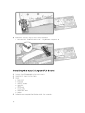
hard drive e. keyboard c. battery 4. access panel g. Connect the I /O) Board 1. Installing the Input/Output (I /O board cable to the system board. 2. Install: a. optical-disk drive h. 4. Disconnect the I /O board into the chassis. 3. Install the I /O board cable and lift it away from the computer [1,2]. base cover b. WLAN card f. Follow the procedures in the illustration: a. Perform the following steps as shown in After Working Inside Your computer . 18 memory module d.
hard drive e. keyboard c. battery 4. access panel g. Connect the I /O) Board 1. Installing the Input/Output (I /O board cable to the system board. 2. Install: a. optical-disk drive h. 4. Disconnect the I /O board into the chassis. 3. Install the I /O board cable and lift it away from the computer [1,2]. base cover b. WLAN card f. Follow the procedures in the illustration: a. Perform the following steps as shown in After Working Inside Your computer . 18 memory module d.

Dell Vostro 153558 Owners Manual
Page 19
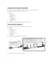
Follow the procedures in the illustration: a. Disconnect the system fan cable from the system board. 19 b. Remove the heatsink assembly from the system board [1]. base cover 3. Perform the following steps as shown in Before Working Inside Your Computer. 2. memory module f. access panel d. battery b. optical-disk drive c. keyboard g. Remove: a. Removing the Heatsink Assembly 1. hard drive e. Remove the screws that secure the heatsink assembly to the system board. 4.
Follow the procedures in the illustration: a. Disconnect the system fan cable from the system board. 19 b. Remove the heatsink assembly from the system board [1]. base cover 3. Perform the following steps as shown in Before Working Inside Your Computer. 2. memory module f. access panel d. battery b. optical-disk drive c. keyboard g. Remove: a. Removing the Heatsink Assembly 1. hard drive e. Remove the screws that secure the heatsink assembly to the system board. 4.
Dell Vostro 153558 Owners Manual
Page 20
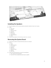
WLAN card f. access panel g. battery 4. Install: a. base cover b. battery b. keyboard g. Lift and remove the speakers from the retention tabs. 4. keyboard c. Follow the procedures in After Working Inside Your computer . Remove: a. Release the speaker cables ...
WLAN card f. access panel g. battery 4. Install: a. base cover b. battery b. keyboard g. Lift and remove the speakers from the retention tabs. 4. keyboard c. Follow the procedures in After Working Inside Your computer . Remove: a. Release the speaker cables ...
Dell Vostro 153558 Owners Manual
Page 21
... procedures in the illustration: a. keyboard h. Installing the Speakers 1. memory module d. hard drive e. optical-disk drive h. access panel d. Disconnect the touchpad and power button cable [2]. 21 battery 3. optical-disk drive c. Remove: a. access panel g. Insert the speakers into the chassis and press along the retention clips to release the locking tab [1]. Install: a. base...
... procedures in the illustration: a. keyboard h. Installing the Speakers 1. memory module d. hard drive e. optical-disk drive h. access panel d. Disconnect the touchpad and power button cable [2]. 21 battery 3. optical-disk drive c. Remove: a. access panel g. Insert the speakers into the chassis and press along the retention clips to release the locking tab [1]. Install: a. base...
Dell Vostro 153558 Owners Manual
Page 24
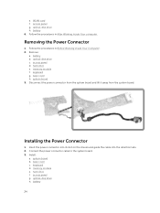
optical-disk drive h. battery 6. Removing the Power Connector 1. battery b. optical-disk drive c. hard drive e. system board 3. optical-disk drive h. e. WLAN card f. Follow the procedures in Before Working Inside Your Computer. 2. memory module f. system board b. ... h. keyboard d. Remove: a. Install: a. Follow the procedures in After Working Inside Your computer. Connect the power connector cable to the system board. 3. Installing the Power Connector 1. battery 24
optical-disk drive h. battery 6. Removing the Power Connector 1. battery b. optical-disk drive c. hard drive e. system board 3. optical-disk drive h. e. WLAN card f. Follow the procedures in Before Working Inside Your Computer. 2. memory module f. system board b. ... h. keyboard d. Remove: a. Install: a. Follow the procedures in After Working Inside Your computer. Connect the power connector cable to the system board. 3. Installing the Power Connector 1. battery 24
Dell Vostro 153558 Owners Manual
Page 25
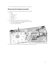
Follow the procedures in the illustration: a. Removing the Display Assembly 1. memory module f. Remove: a. access panel d. hard drive e. Perform the following steps as shown in Before Working Inside Your Computer. 2. c. Remove the hinge screws that secure the display assembly to the computer. 25 b. 4. Follow the procedures in After Working Inside Your computer . optical-disk drive c. keyboard 3. Unroute the WLAN cable [4]. 4. Unroute the display assembly cable [3]. battery b. Lift the tab and disconnect the display assembly cable [1] [2].
Follow the procedures in the illustration: a. Removing the Display Assembly 1. memory module f. Remove: a. access panel d. hard drive e. Perform the following steps as shown in Before Working Inside Your Computer. 2. c. Remove the hinge screws that secure the display assembly to the computer. 25 b. 4. Follow the procedures in After Working Inside Your computer . optical-disk drive c. keyboard 3. Unroute the WLAN cable [4]. 4. Unroute the display assembly cable [3]. battery b. Lift the tab and disconnect the display assembly cable [1] [2].
Dell Vostro 153558 Owners Manual
Page 27
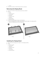
...: a. memory module e. Removing the Display Bezel 1. optical-disk drive c. keyboard g. display assembly 3. Follow the procedures in After Working Inside Your computer. access panel g. battery b. system board h. keyboard d. hard drive f. battery 4. memory module f. b. access panel d. Remove the display bezel from the computer [2]. Installing the Display Bezel 1. f. Place the display panel on a stable surface...
...: a. memory module e. Removing the Display Bezel 1. optical-disk drive c. keyboard g. display assembly 3. Follow the procedures in After Working Inside Your computer. access panel g. battery b. system board h. keyboard d. hard drive f. battery 4. memory module f. b. access panel d. Remove the display bezel from the computer [2]. Installing the Display Bezel 1. f. Place the display panel on a stable surface...
Dell Vostro 153558 Owners Manual
Page 28
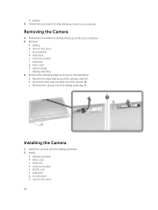
... that secures the camera cable [1]. optical-disk drive 28 Perform the following steps as shown in After Working Inside Your computer . memory module e. hard drive g. battery 3. Remove: a. hard drive e. memory module f. keyboard d. Follow the procedures in Before Working Inside Your Computer. 2. Disconnect the camera cable from the display assembly [3]. access panel...
... that secures the camera cable [1]. optical-disk drive 28 Perform the following steps as shown in After Working Inside Your computer . memory module e. hard drive g. battery 3. Remove: a. hard drive e. memory module f. keyboard d. Follow the procedures in Before Working Inside Your Computer. 2. Disconnect the camera cable from the display assembly [3]. access panel...
Dell Vostro 153558 Owners Manual
Page 29
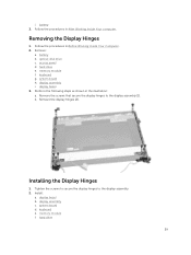
... Hinges 1. Follow the procedures in Before Working Inside Your Computer. 2. Remove: a. hard drive e. Remove the screws that secure the display hinges to the display assembly. 2. battery b. b. i. memory module f. battery 3. display assembly i. Tighten the screws to secure the display hinges to the display assembly [1]. system board d.
... Hinges 1. Follow the procedures in Before Working Inside Your Computer. 2. Remove: a. hard drive e. Remove the screws that secure the display hinges to the display assembly. 2. battery b. b. i. memory module f. battery 3. display assembly i. Tighten the screws to secure the display hinges to the display assembly [1]. system board d.

