
Owner's Manual
Page 23
Remove the battery. 3. Removing The Palm Rest 8 1. Remove the screws that secure the palm rest to the computer. 23 Remove the screws that secure the bottom base. 5. Flip the computer around and disconnect the power board cable (1) and the touchpad cable (2). 6. Remove the keyboard. 4. Follow the procedures in Before Working On Your Computer. 2.
Remove the battery. 3. Removing The Palm Rest 8 1. Remove the screws that secure the palm rest to the computer. 23 Remove the screws that secure the bottom base. 5. Flip the computer around and disconnect the power board cable (1) and the touchpad cable (2). 6. Remove the keyboard. 4. Follow the procedures in Before Working On Your Computer. 2.

Owner's Manual
Page 25
Connect the power board cable and touchpad cable to secure all the snaps. 3. Align and adjust the palm rest into position before pressing it down to their respective connectors. 4. Install the battery. 8. Installing The Palm Rest 1. Insert the palm rest towards the display screen at a 30-degree angle. 2. Install the keyboard. 7. Follow the procedures in After Working Inside Your Computer. 25 Flip the computer around and install the screws that secure the palm rest to the computer. 5. Install the screws that secure the bottom base. 6.
Connect the power board cable and touchpad cable to secure all the snaps. 3. Align and adjust the palm rest into position before pressing it down to their respective connectors. 4. Install the battery. 8. Installing The Palm Rest 1. Insert the palm rest towards the display screen at a 30-degree angle. 2. Install the keyboard. 7. Follow the procedures in After Working Inside Your Computer. 25 Flip the computer around and install the screws that secure the palm rest to the computer. 5. Install the screws that secure the bottom base. 6.

Setup and Features Information Tech Sheet
Page 2
Back View 1. security cable slot 2. network connector 6. 7. optical drive eject button 8. audio connectors 9. memory card reader 12. touchpad buttons (2) 13. battery 3. power connector 4. keyboard 15. cooling vents 5. VGA connector 7. Restricting the airflow can damage the computer ...fire. The computer turns on the fan when the computer gets hot. Do not store your Dell computer in the air vents. microphone 10. Fan noise is running. device status lights 14. touchpad 11. power button Figure 2. HDMI connector 8. USB 2.0 connector WARNING: Do not block, push...
Back View 1. security cable slot 2. network connector 6. 7. optical drive eject button 8. audio connectors 9. memory card reader 12. touchpad buttons (2) 13. battery 3. power connector 4. keyboard 15. cooling vents 5. VGA connector 7. Restricting the airflow can damage the computer ...fire. The computer turns on the fan when the computer gets hot. Do not store your Dell computer in the air vents. microphone 10. Fan noise is running. device status lights 14. touchpad 11. power button Figure 2. HDMI connector 8. USB 2.0 connector WARNING: Do not block, push...

Setup and Features Information Tech Sheet
Page 3
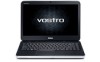
camera status light 2. touchpad buttons (2) 10. keyboard 14. Vostro 1540/1550 Figure 3. speakers (2) 5. touchpad 9. memory card reader 12. Front And Back - camera 3. microphone 11. power button 3 display 4. USB 2.0 connectors (2) 8. optical drive 6. optical drive eject button 7. Front View 1. device status lights 13.
camera status light 2. touchpad buttons (2) 10. keyboard 14. Vostro 1540/1550 Figure 3. speakers (2) 5. touchpad 9. memory card reader 12. Front And Back - camera 3. microphone 11. power button 3 display 4. USB 2.0 connectors (2) 8. optical drive 6. optical drive eject button 7. Front View 1. device status lights 13.


