Setup and Features Information Tech Sheet
Page 2
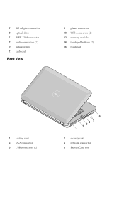
7 AC adapter connector 9 optical drive 11 IEEE 1394 connector 13 audio connectors (2) 15 indicator lens 17 keyboard Back View 8 phone connector 10 USB connectors (2) 12 memory card slot 14 touchpad buttons (2) 16 touchpad 1 cooling vent 3 VGA connector 5 USB connectors (2) 6 2 34 5 1 2 security slot 4 network connector 6 ExpressCard slot
7 AC adapter connector 9 optical drive 11 IEEE 1394 connector 13 audio connectors (2) 15 indicator lens 17 keyboard Back View 8 phone connector 10 USB connectors (2) 12 memory card slot 14 touchpad buttons (2) 16 touchpad 1 cooling vent 3 VGA connector 5 USB connectors (2) 6 2 34 5 1 2 security slot 4 network connector 6 ExpressCard slot

Setup and Features Information Tech Sheet
Page 4
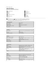
...Intel Celeron®(Socket P) Video Video type integrated on system board, hardware accelerated Data bus integrated video Video controller Intel GM45 Video memory integrated graphics System memory Dynamic Video Memory Technology (DVMT) 1 GB - 2 GB - 3 GB - 4 GB - 512 MB 782 MB 1294 MB 1550 MB...responds to system requirements and application's demands by law to ship with your computer. For more information regarding the configuration of memory for balanced graphics and system performance. Specifications NOTE: Offerings may vary by region. 5 Open the computer display and press...
...Intel Celeron®(Socket P) Video Video type integrated on system board, hardware accelerated Data bus integrated video Video controller Intel GM45 Video memory integrated graphics System memory Dynamic Video Memory Technology (DVMT) 1 GB - 2 GB - 3 GB - 4 GB - 512 MB 782 MB 1294 MB 1550 MB...responds to system requirements and application's demands by law to ship with your computer. For more information regarding the configuration of memory for balanced graphics and system performance. Specifications NOTE: Offerings may vary by region. 5 Open the computer display and press...
Setup and Features Information Tech Sheet
Page 5
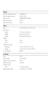
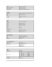
Memory Memory module connector Memory module capacity Memory type: Minimum memory Maximum memory Battery Type Dimensions: Depth Height Width Voltage: 4-cell 6-cell Temperature range: Operating Storage Coin-cell battery AC Adapter Type Input voltage Input current (maximum) Input ...
Memory Memory module connector Memory module capacity Memory type: Minimum memory Maximum memory Battery Type Dimensions: Depth Height Width Voltage: 4-cell 6-cell Temperature range: Operating Storage Coin-cell battery AC Adapter Type Input voltage Input current (maximum) Input ...
Service Manual
Page 23
For additional safety best practices information, see the Regulatory Compliance Homepage at www.dell.com/regulatory_compliance. Remove the battery. 5. Remove the access panel. 6. Remove the memory modules. 8. Remove the WLAN card. 9. Remove the display assembly. 12. Remove the ExpressCard (if applicable). 3. ...procedures in the illustration below to loosen the four screws that secure the heat sink to Contents Page Heat Sink Dell™ Vostro™ 1014/1015 Service Manual WARNING: Before working inside your computer, read the safety information that shipped with your computer. ...
For additional safety best practices information, see the Regulatory Compliance Homepage at www.dell.com/regulatory_compliance. Remove the battery. 5. Remove the access panel. 6. Remove the memory modules. 8. Remove the WLAN card. 9. Remove the display assembly. 12. Remove the ExpressCard (if applicable). 3. ...procedures in the illustration below to loosen the four screws that secure the heat sink to Contents Page Heat Sink Dell™ Vostro™ 1014/1015 Service Manual WARNING: Before working inside your computer, read the safety information that shipped with your computer. ...
Service Manual
Page 40
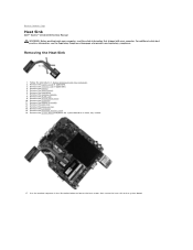
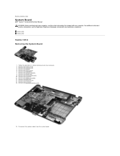
... the system board. Remove the ExpressCard. 3. Remove the memory card. 4. Remove the hard drive. 7. Remove the memory modules. 8. Remove the keyboard. 11. Remove the I/O board. 15. Vostro 1014 Vostro 1015 Vostro 1014 Removing the System Board 1. Remove the access panel. 6.... Remove the Bluetooth wireless card. 16. For additional safety best practices information, see the Regulatory Compliance Homepage at www.dell...
... the system board. Remove the ExpressCard. 3. Remove the memory card. 4. Remove the hard drive. 7. Remove the memory modules. 8. Remove the keyboard. 11. Remove the I/O board. 15. Vostro 1014 Vostro 1015 Vostro 1014 Removing the System Board 1. Remove the access panel. 6.... Remove the Bluetooth wireless card. 16. For additional safety best practices information, see the Regulatory Compliance Homepage at www.dell...
Service Manual
Page 43
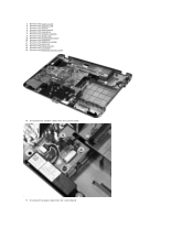
Remove the keyboard. 11. Remove the Bluetooth wireless card. 16. 2. Remove the ExpressCard. 3. Remove the battery. 5. Remove the memory modules. 8. Remove the display assembly. 12. Remove the control panel cover. 10. Remove the I/O board. 15. Remove the access panel. 6. Remove the hard drive. 7. Remove the WLAN card. 9. Remove the memory card. 4. Remove the palm rest. 13. Disconnect the speaker cables from the system board. Disconnect the power cable from the system board. 17. Remove the processor fan. 14.
Remove the keyboard. 11. Remove the Bluetooth wireless card. 16. 2. Remove the ExpressCard. 3. Remove the battery. 5. Remove the memory modules. 8. Remove the display assembly. 12. Remove the control panel cover. 10. Remove the I/O board. 15. Remove the access panel. 6. Remove the hard drive. 7. Remove the WLAN card. 9. Remove the memory card. 4. Remove the palm rest. 13. Disconnect the speaker cables from the system board. Disconnect the power cable from the system board. 17. Remove the processor fan. 14.

Service Manual
Page 46
... best practices information, see the Regulatory Compliance Homepage at www.dell.com/regulatory_compliance. Removing Memory Modules 1. Remove the battery. 3. Remove the access panel. 4. Slide the first memory module from its socket and remove the module from the computer. Back to Contents Page Memory Dell™ Vostro™ 1014/1015 Service Manual WARNING: Before working inside your computer...
... best practices information, see the Regulatory Compliance Homepage at www.dell.com/regulatory_compliance. Removing Memory Modules 1. Remove the battery. 3. Remove the access panel. 4. Slide the first memory module from its socket and remove the module from the computer. Back to Contents Page Memory Dell™ Vostro™ 1014/1015 Service Manual WARNING: Before working inside your computer...
Service Manual
Page 47
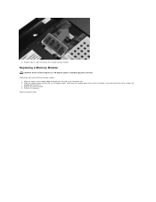
Replacing a Memory Module CAUTION: Insert memory modules at a 45-degree angle, and rotate the module down until it . 3. Slide the module firmly into place. 6. Replace the access panel. 4. Back to remove the second memory module. If you do not feel the click, remove the module and reinstall it clicks into the slot at a 45-degree angle to avoid damaging the connector. Ground yourself and install the memory module: 1. Align the notch in the module edge connector with the tab in the connector slot. 2. Repeat steps 4 and 5 to Contents Page Replace the battery.
Replacing a Memory Module CAUTION: Insert memory modules at a 45-degree angle, and rotate the module down until it . 3. Slide the module firmly into place. 6. Replace the access panel. 4. Back to remove the second memory module. If you do not feel the click, remove the module and reinstall it clicks into the slot at a 45-degree angle to avoid damaging the connector. Ground yourself and install the memory module: 1. Align the notch in the module edge connector with the tab in the connector slot. 2. Repeat steps 4 and 5 to Contents Page Replace the battery.

Service Manual
Page 48
Slide the memory card from the memory card slot in Before Working Inside Your Computer. 2. Press the memory card to Contents Page Memory Card Dell™ Vostro™ 1014/1015 Service Manual WARNING: Before working inside your computer, read the safety information that shipped with your computer. Follow the procedures in the computer. 3. Removing the Memory Card 1. For additional safety best practices information, see the Regulatory Compliance Homepage at www.dell.com/regulatory_compliance. Back to release it from the computer.
Slide the memory card from the memory card slot in Before Working Inside Your Computer. 2. Press the memory card to Contents Page Memory Card Dell™ Vostro™ 1014/1015 Service Manual WARNING: Before working inside your computer, read the safety information that shipped with your computer. Follow the procedures in the computer. 3. Removing the Memory Card 1. For additional safety best practices information, see the Regulatory Compliance Homepage at www.dell.com/regulatory_compliance. Back to release it from the computer.

Service Manual
Page 49
Back to replace a memory card. Replacing the Memory Card Perform the above steps in the reverse to Contents Page
Back to replace a memory card. Replacing the Memory Card Perform the above steps in the reverse to Contents Page
Service Manual
Page 58
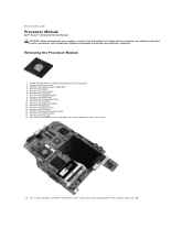
..., flat-blade screwdriver and rotate the ZIF-socket cam screw counterclockwise until it comes to Contents Page Processor Module Dell™ Vostro™ 1014/1015 Service Manual WARNING: Before working inside your computer, read the safety information that shipped with your computer. ...additional safety best practices information, see the Regulatory Compliance Homepage at www.dell.com/regulatory_compliance. Remove the keyboard. 11. Remove the Bluetooth wireless card. 16. Remove the processor fan. 14. Remove the memory card (if applicable). 4. Set aside the computer chassis and place...
..., flat-blade screwdriver and rotate the ZIF-socket cam screw counterclockwise until it comes to Contents Page Processor Module Dell™ Vostro™ 1014/1015 Service Manual WARNING: Before working inside your computer, read the safety information that shipped with your computer. ...additional safety best practices information, see the Regulatory Compliance Homepage at www.dell.com/regulatory_compliance. Remove the keyboard. 11. Remove the Bluetooth wireless card. 16. Remove the processor fan. 14. Remove the memory card (if applicable). 4. Set aside the computer chassis and place...
Service Manual
Page 60
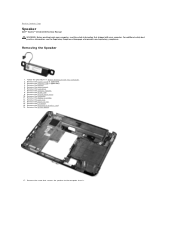
... that shipped with your computer, read the safety information that secures the speaker to Contents Page Speaker Dell™ Vostro™ 1014/1015 Service Manual WARNING: Before working inside your computer. For additional safety best practices information, see the Regulatory... Compliance Homepage at www.dell.com/regulatory_compliance. Remove the memory card (if applicable). 4. Remove the Bluetooth® wireless card. 16. Remove the ...
... that shipped with your computer, read the safety information that secures the speaker to Contents Page Speaker Dell™ Vostro™ 1014/1015 Service Manual WARNING: Before working inside your computer. For additional safety best practices information, see the Regulatory... Compliance Homepage at www.dell.com/regulatory_compliance. Remove the memory card (if applicable). 4. Remove the Bluetooth® wireless card. 16. Remove the ...

Service Manual
Page 65
...l System Information ¡ BIOS Version ¡ Service Tag ¡ Asset Tag ¡ Ownership Tag l Memory Information ¡ Memory Installed ¡ Memory Available ¡ Memory Speed ¡ Memory Channel Mode ¡ Memory Technology ¡ DIMM A Size ¡ DIMM B Size l Processor Information ¡ Processor Type ¡... Device Information ¡ Primary Hard Drive ¡ Fixed Bay Device ¡ Video Controller ¡ Video BIOS Version ¡ Video Memory ¡ Panel Type ¡ Native Resolution ¡ Audio Controller ¡ Modem Controller ¡ Wi-Fi Device ¡ Bluetooth&#...
...l System Information ¡ BIOS Version ¡ Service Tag ¡ Asset Tag ¡ Ownership Tag l Memory Information ¡ Memory Installed ¡ Memory Available ¡ Memory Speed ¡ Memory Channel Mode ¡ Memory Technology ¡ DIMM A Size ¡ DIMM B Size l Processor Information ¡ Processor Type ¡... Device Information ¡ Primary Hard Drive ¡ Fixed Bay Device ¡ Video Controller ¡ Video BIOS Version ¡ Video Memory ¡ Panel Type ¡ Native Resolution ¡ Audio Controller ¡ Modem Controller ¡ Wi-Fi Device ¡ Bluetooth&#...

Service Manual
Page 67
... can only be able to set . If a Service Tag has not been set for some compatibility steps. Boot quickly unless the BIOS has been updated, memory changed, or the previous POST did not complete. Fn Key Emulation Fast Boot Default setting: Enabled This field lets you use the key on an...
... can only be able to set . If a Service Tag has not been set for some compatibility steps. Boot quickly unless the BIOS has been updated, memory changed, or the previous POST did not complete. Fn Key Emulation Fast Boot Default setting: Enabled This field lets you use the key on an...
Service Manual
Page 68
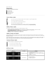
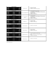
...Alternately blinking amber light and blue light - Appearance ON-FLASH-FLASH Description No SODIMMs are on when wireless networking is enabled. If memory is attached to your laptop. Replace the system board. Turns on , the battery has 80 percent of the total battery charge....each slot. 3. Each light represents approximately 20 percent of its original charge capacity remains. Back to Contents Page Diagnostics Dell™ Vostro™ 1014/1015 Service Manual Device Status Lights Battery Status Lights Battery Charge and Health Keyboard Status Lights LED Error Codes Device Status ...
...Alternately blinking amber light and blue light - Appearance ON-FLASH-FLASH Description No SODIMMs are on when wireless networking is enabled. If memory is attached to your laptop. Replace the system board. Turns on , the battery has 80 percent of the total battery charge....each slot. 3. Each light represents approximately 20 percent of its original charge capacity remains. Back to Contents Page Diagnostics Dell™ Vostro™ 1014/1015 Service Manual Device Status Lights Battery Status Lights Battery Charge and Health Keyboard Status Lights LED Error Codes Device Status ...
Service Manual
Page 69
... Reseat the hard drive and optical drive. 2. Test the computer with both modules. 3. Reseat the memory. 2. Replace the memory. 4. System board error 1. Replace the system board. Memory compatibility error 1. Try the other slot with both modules. 3. FLASH-ON-FLASH OFF-FLASH-OFF ON-...board. Modem error 1. Replace the LCD panel. 3. Storage device error 1. Replace the system board. Replace the system board. Install compatible memory modules. 2. Option ROM error 1. Replace the device. 3. Try the other slot with just the hard drive and just the optical drive...
... Reseat the hard drive and optical drive. 2. Test the computer with both modules. 3. Reseat the memory. 2. Replace the memory. 4. System board error 1. Replace the system board. Memory compatibility error 1. Try the other slot with both modules. 3. FLASH-ON-FLASH OFF-FLASH-OFF ON-...board. Modem error 1. Replace the LCD panel. 3. Storage device error 1. Replace the system board. Replace the system board. Install compatible memory modules. 2. Option ROM error 1. Replace the device. 3. Try the other slot with just the hard drive and just the optical drive...
Service Manual
Page 70
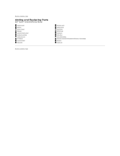
Back to Contents Page Adding and Replacing Parts Dell™ Vostro™ 1014/1015 Service Manual ExpressCard Battery Access Panel Memory Control Panel Cover Display Assembly Processor Fan I/O Board System Board Heat Sink Back to Contents Page Memory Card Optical Drive Hard Drive WLAN Card Keyboard Palm Rest Coin-Cell Battery Internal Card with Bluetooth® Wireless Technology Speaker Processor
Back to Contents Page Adding and Replacing Parts Dell™ Vostro™ 1014/1015 Service Manual ExpressCard Battery Access Panel Memory Control Panel Cover Display Assembly Processor Fan I/O Board System Board Heat Sink Back to Contents Page Memory Card Optical Drive Hard Drive WLAN Card Keyboard Palm Rest Coin-Cell Battery Internal Card with Bluetooth® Wireless Technology Speaker Processor
Service Manual
Page 71
...in Windows® XP)® Help and Support, and then select the option to Contents Page Specifications Dell™ Vostro™ 1014/1015 Service Manual System Information Memory Audio Battery 5-in connector, stereo headphones/speakers mini-connector Back to view information about your computer. ...frequency Intel Core 2 Duo, or Intel Celeron® processors (Socket P) 3 MB or 6 MB 667 and 800 MHz Memory Memory module connectors Memory module capacities Memory type Minimum memory Maximum memory two DIMM sockets 1 (one DIMM), 2 (one DIMM or two DIMMs), or 4 GB (two DIMMs) capable DDR2...
...in Windows® XP)® Help and Support, and then select the option to Contents Page Specifications Dell™ Vostro™ 1014/1015 Service Manual System Information Memory Audio Battery 5-in connector, stereo headphones/speakers mini-connector Back to view information about your computer. ...frequency Intel Core 2 Duo, or Intel Celeron® processors (Socket P) 3 MB or 6 MB 667 and 800 MHz Memory Memory module connectors Memory module capacities Memory type Minimum memory Maximum memory two DIMM sockets 1 (one DIMM), 2 (one DIMM or two DIMMs), or 4 GB (two DIMMs) capable DDR2...
Service Manual
Page 72
...PCI ExpressCard four USB 2.0-compliant connectors 15-hole connectors 4-pin mini Ricoh R5C847 3-in -1 Memory Card Reader Media card controller Connector Cards supported Video Video type Video controller Video memory LCD interface TV support one 2-watt, 4-ohm speaker 2-W channel into 4 ohms single digital ...ExpressCard connector USB Video IEEE 1394 5-in -1 combo card connector SecureDigital (SD) SDIO MultiMediaCard(MMC) Memory Stick Memory Stick PRO integrated Intel GM45 System Memory 1 GB 2 GB 3 GB 4 GB LVDS VGA connector Dynamic Video Memory Technology (DVMT) 512 MB 782 MB 1294 MB 1550 MB
...PCI ExpressCard four USB 2.0-compliant connectors 15-hole connectors 4-pin mini Ricoh R5C847 3-in -1 Memory Card Reader Media card controller Connector Cards supported Video Video type Video controller Video memory LCD interface TV support one 2-watt, 4-ohm speaker 2-W channel into 4 ohms single digital ...ExpressCard connector USB Video IEEE 1394 5-in -1 combo card connector SecureDigital (SD) SDIO MultiMediaCard(MMC) Memory Stick Memory Stick PRO integrated Intel GM45 System Memory 1 GB 2 GB 3 GB 4 GB LVDS VGA connector Dynamic Video Memory Technology (DVMT) 512 MB 782 MB 1294 MB 1550 MB


