Microsoft Windows 7: Getting Started Guide
Page 1
...may take you through several procedures including accepting license agreements, setting preferences, and setting up Windows for your computer available at support.dell.com. If an external USB modem or WLAN adapter is recommended that you download and install the latest BIOS and drivers for...process. These steps are mandatory and may render your original order, you can purchase one at www.dell.com. October 2009 Microsoft Windows 7: Getting Started Guide Set Up Windows 7 Your Dell computer is preconfigured with the Microsoft® Windows® 7 operating system if you selected it is...
...may take you through several procedures including accepting license agreements, setting preferences, and setting up Windows for your computer available at support.dell.com. If an external USB modem or WLAN adapter is recommended that you download and install the latest BIOS and drivers for...process. These steps are mandatory and may render your original order, you can purchase one at www.dell.com. October 2009 Microsoft Windows 7: Getting Started Guide Set Up Windows 7 Your Dell computer is preconfigured with the Microsoft® Windows® 7 operating system if you selected it is...

Microsoft Windows 7: Getting Started Guide
Page 2
Setting Up a Wireless Connection Before you can help you need to connect to your wireless router. To set up your connection to a wireless router: 1 Ensure that wireless is enabled on your computer. 2 Save and close any open files, and exit any open programs. 2 Click Start → Control Panel 3 Click Network and Sharing Center→ Set up a new connection or network→ Connect to the Internet. To complete setting up your country. Setting Up Your Internet Connection ISPs and ISP offerings vary by country. To set up your Internet connection: 1 Save and close any open files, and...
Setting Up a Wireless Connection Before you can help you need to connect to your wireless router. To set up your connection to a wireless router: 1 Ensure that wireless is enabled on your computer. 2 Save and close any open files, and exit any open programs. 2 Click Start → Control Panel 3 Click Network and Sharing Center→ Set up a new connection or network→ Connect to the Internet. To complete setting up your country. Setting Up Your Internet Connection ISPs and ISP offerings vary by country. To set up your Internet connection: 1 Save and close any open files, and...
Microsoft Windows 7: Getting Started Guide
Page 3
NOTE: If you periodically back up backup.... 3 Follow the instructions on the Configure Backup wizard. 3 Transferring Information to a New Computer To transfer information to a new computer: 1 Click Start → Control Panel. 2 In the search box, type Transfer and then click Transfer files from another computer. 3 Follow the instructions on the screen and use the setup information provided by your computer. To customize your desktop: 1 Right-click an open area of the desktop. 2 Click Personalize, to open the Change the visuals and sounds on your ISP to select, click Help me choose ...
NOTE: If you periodically back up backup.... 3 Follow the instructions on the Configure Backup wizard. 3 Transferring Information to a New Computer To transfer information to a new computer: 1 Click Start → Control Panel. 2 In the search box, type Transfer and then click Transfer files from another computer. 3 Follow the instructions on the screen and use the setup information provided by your computer. To customize your desktop: 1 Right-click an open area of the desktop. 2 Click Personalize, to open the Change the visuals and sounds on your ISP to select, click Help me choose ...
Microsoft Windows 7: Getting Started Guide
Page 4
...or other countries. To reinstall Windows 7: 1 Save and close any open files and exit any manner whatsoever without notice. © 2009 Dell Inc. Follow the instructions on the screen to complete. is subject to Boot from CD-ROM. Reinstalling Windows 7 The reinstallation process may... be used in this text: Dell and the DELL logo are either the entities claiming the marks and names or their products. After you reinstall the operating system, you must ...
...or other countries. To reinstall Windows 7: 1 Save and close any open files and exit any manner whatsoever without notice. © 2009 Dell Inc. Follow the instructions on the screen to complete. is subject to Boot from CD-ROM. Reinstalling Windows 7 The reinstallation process may... be used in this text: Dell and the DELL logo are either the entities claiming the marks and names or their products. After you reinstall the operating system, you must ...
Service Manual
Page 1
Dell Studio™ Slim 540s Service Manual Technical Overview Before You Begin Replacing the Computer Cover Replacing the Support Bracket Replacing the Front Panel Replacing Memory Module(s) Replacing PCI/... the United States and/or other countries.; Reproduction of these materials in any proprietary interest in this text: Dell, the DELL logo, and Dell Studio are either the entities claiming the marks and names or their products. Dell Inc. and other countries. A00 CAUTION: A CAUTION indicates a potential for property damage, personal injury, or death. Trademarks...
Dell Studio™ Slim 540s Service Manual Technical Overview Before You Begin Replacing the Computer Cover Replacing the Support Bracket Replacing the Front Panel Replacing Memory Module(s) Replacing PCI/... the United States and/or other countries.; Reproduction of these materials in any proprietary interest in this text: Dell, the DELL logo, and Dell Studio are either the entities claiming the marks and names or their products. Dell Inc. and other countries. A00 CAUTION: A CAUTION indicates a potential for property damage, personal injury, or death. Trademarks...
Service Manual
Page 2
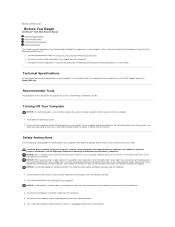
...; CAUTION: Before working inside your computer, read the safety information that the work surface is flat and clean to Contents Page Before You Begin Dell Studio™ Slim 540s Service Manual Technical Specifications Recommended Tools Turning Off Your Computer Safety Instructions This chapter provides procedures for removing and installing the components in your...
...; CAUTION: Before working inside your computer, read the safety information that the work surface is flat and clean to Contents Page Before You Begin Dell Studio™ Slim 540s Service Manual Technical Specifications Recommended Tools Turning Off Your Computer Safety Instructions This chapter provides procedures for removing and installing the components in your...

Service Manual
Page 3
NOTICE: Before touching anything inside your computer, ground yourself by touching an unpainted metal surface, such as the metal at the back of the computer. While you work, periodically touch an unpainted metal surface to Contents Page Back to dissipate static electricity, which could harm internal components.
NOTICE: Before touching anything inside your computer, ground yourself by touching an unpainted metal surface, such as the metal at the back of the computer. While you work, periodically touch an unpainted metal surface to Contents Page Back to dissipate static electricity, which could harm internal components.

Service Manual
Page 4
... 11. Pivot the support bracket and lift it down. 9. To replace the support bracket, align and insert the hinges at www.dell.com/regulatory_compliance. 1. Replace any cable(s) attached to the support bracket. 5. Ensure that were attached to the support bracket. 10. ...support bracket into the hinge tabs located along the edge of the computer. 7. Back to Contents Page Replacing the Support Bracket Dell Studio™ Slim 540s Service Manual CAUTION: Before working inside your computer. Replace the computer cover (see Replacing the Computer Cover). 1 support bracket...
... 11. Pivot the support bracket and lift it down. 9. To replace the support bracket, align and insert the hinges at www.dell.com/regulatory_compliance. 1. Replace any cable(s) attached to the support bracket. 5. Ensure that were attached to the support bracket. 10. ...support bracket into the hinge tabs located along the edge of the computer. 7. Back to Contents Page Replacing the Support Bracket Dell Studio™ Slim 540s Service Manual CAUTION: Before working inside your computer. Replace the computer cover (see Replacing the Computer Cover). 1 support bracket...
Service Manual
Page 5
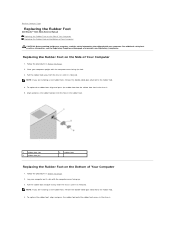
... side. 3. Pull the rubber foot and pull it away from the chassis until it is released. Back to Contents Page Replacing the Rubber Foot Dell Studio™ Slim 540s Service Manual Replacing the Rubber Foot on the Side of Your Computer Replacing the Rubber Foot on its side with the computer cover facing...
... side. 3. Pull the rubber foot and pull it away from the chassis until it is released. Back to Contents Page Replacing the Rubber Foot Dell Studio™ Slim 540s Service Manual Replacing the Rubber Foot on the Side of Your Computer Replacing the Rubber Foot on its side with the computer cover facing...
Service Manual
Page 7
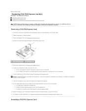
... retention release lever. 1 card retention release lever 2 card retention bracket 5. Back to Contents Page Replacing PCI/PCI Express Card(s) Dell Studio™ Slim 540s Service Manual Removing a PCI/PCI Express Card Installing a PCI/PCI Express Card Configuring Your Computer After Removing or Installing a... removal procedure, see the Setup Guide. 2. For additional safety best practices information, see the Regulatory Compliance Homepage at www.dell.com/regulatory_compliance. Uninstall the card's driver and software from the operating system. The brackets also keep dust and dirt out of...
... retention release lever. 1 card retention release lever 2 card retention bracket 5. Back to Contents Page Replacing PCI/PCI Express Card(s) Dell Studio™ Slim 540s Service Manual Removing a PCI/PCI Express Card Installing a PCI/PCI Express Card Configuring Your Computer After Removing or Installing a... removal procedure, see the Setup Guide. 2. For additional safety best practices information, see the Regulatory Compliance Homepage at www.dell.com/regulatory_compliance. Uninstall the card's driver and software from the operating system. The brackets also keep dust and dirt out of...

Service Manual
Page 8
Remove the computer cover. Align the card with the alignment bar. Place the card in the top of slot 9. l The tops of all cards and filler brackets are installing a PCI Express card into the x16 connector, ensure that the securing slot is aligned with the guide notch. See Replacing the Computer Cover. 3. l Making internal connections. 7. l The notch in the connector and press down the card retention bracket to the equipment. 10. 1. Remove the support bracket (see Replacing the Support Bracket). 5. NOTE: If you are flush with the connector. Prepare the card for ...
Remove the computer cover. Align the card with the alignment bar. Place the card in the top of slot 9. l The tops of all cards and filler brackets are installing a PCI Express card into the x16 connector, ensure that the securing slot is aligned with the guide notch. See Replacing the Computer Cover. 3. l Making internal connections. 7. l The notch in the connector and press down the card retention bracket to the equipment. 10. 1. Remove the support bracket (see Replacing the Support Bracket). 5. NOTE: If you are flush with the connector. Prepare the card for ...

Service Manual
Page 9
Connect the external audio devices to the integrated network connector. Enter system setup (see System Setup). 2. Connect the network cable to the sound card's connectors. 1. Enter system setup (see System Setup). 2. Go to Integrated Peripherals and select Onboard LAN Controller, and then change the setting to Disabled. 3. Replace the computer cover, reconnect the computer and devices to Enabled. 3. To complete the installation, see System Setup). 2. Sound Card Installed Removed 1. Network Card 1. Enter system setup (see Configuring Your Computer After ...
Connect the external audio devices to the integrated network connector. Enter system setup (see System Setup). 2. Connect the network cable to the sound card's connectors. 1. Enter system setup (see System Setup). 2. Go to Integrated Peripherals and select Onboard LAN Controller, and then change the setting to Disabled. 3. Replace the computer cover, reconnect the computer and devices to Enabled. 3. To complete the installation, see System Setup). 2. Sound Card Installed Removed 1. Network Card 1. Enter system setup (see Configuring Your Computer After ...
Service Manual
Page 10
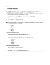
.... 1 battery (positive side) 2 battery release lever 8. Back to the manufacturer's instructions. 1. Back to Contents Page Replacing the Battery Dell Studio™ Slim 540s Service Manual CAUTION: Before working inside your computer, read the safety information that shipped with the side labeled "+" facing up, then snap...the socket before you recorded in step 10. 2. Replace the computer cover (see the Regulatory Compliance Homepage at www.dell.com/regulatory_compliance. Connect your computer. CAUTION: A new battery can restore the correct settings in step 1. Record all the screens in...
.... 1 battery (positive side) 2 battery release lever 8. Back to the manufacturer's instructions. 1. Back to Contents Page Replacing the Battery Dell Studio™ Slim 540s Service Manual CAUTION: Before working inside your computer, read the safety information that shipped with the side labeled "+" facing up, then snap...the socket before you recorded in step 10. 2. Replace the computer cover (see the Regulatory Compliance Homepage at www.dell.com/regulatory_compliance. Connect your computer. CAUTION: A new battery can restore the correct settings in step 1. Record all the screens in...
Service Manual
Page 11
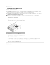
... down and slide the computer cover towards the front of the computer. 7. Back to Contents Page Replacing the Computer Cover Dell Studio™ Slim 540s Service Manual CAUTION: Before working inside your computer, read the safety information that sufficient space exists to Contents Page Lay...is securely installed. 8. Replace the two screws that secure the computer cover. Back to support the system with the cover removed-at www.dell.com/regulatory_compliance. Remove the two screws securing the cover, using a flat-blade screwdriver. 1 computer cover 2 screws (2) 4. Slide the ...
... down and slide the computer cover towards the front of the computer. 7. Back to Contents Page Replacing the Computer Cover Dell Studio™ Slim 540s Service Manual CAUTION: Before working inside your computer, read the safety information that sufficient space exists to Contents Page Lay...is securely installed. 8. Replace the two screws that secure the computer cover. Back to support the system with the cover removed-at www.dell.com/regulatory_compliance. Remove the two screws securing the cover, using a flat-blade screwdriver. 1 computer cover 2 screws (2) 4. Slide the ...
Service Manual
Page 12
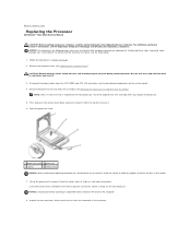
...not to cool before you are familiar with your system board. Remove the computer cover (see the Regulatory Compliance Homepage at www.dell.com/regulatory_compliance. Follow the procedures in the release position so that the socket is required for the new processor. Open the processor... extended in Before You Begin. 2. Performing these steps incorrectly could damage your computer. Back to Contents Page Replacing the Processor Dell Studio™ Slim 540s Service Manual CAUTION: Before working inside the socket or allow any of the pins inside your computer, read the safety ...
...not to cool before you are familiar with your system board. Remove the computer cover (see the Regulatory Compliance Homepage at www.dell.com/regulatory_compliance. Follow the procedures in the release position so that the socket is required for the new processor. Open the processor... extended in Before You Begin. 2. Performing these steps incorrectly could damage your computer. Back to Contents Page Replacing the Processor Dell Studio™ Slim 540s Service Manual CAUTION: Before working inside the socket or allow any of the pins inside your computer, read the safety ...

Service Manual
Page 13
Be careful not to the top of the processor. 17. When the processor is positioned underneath the center cover latch on the processor cover is fully seated in the socket, close the processor cover. Ensure that the tab on the socket. 14. Apply the new thermal grease to touch or bend the pins on the computer. Connect the power cables from the bottom of the processor and socket. Back to secure the processor. 15. Place the processor lightly in the socket to avoid permanent damage to electrical outlets, and then turn on the system board. 10. Pivot the socket release lever back ...
Be careful not to the top of the processor. 17. When the processor is positioned underneath the center cover latch on the processor cover is fully seated in the socket, close the processor cover. Ensure that the tab on the socket. 14. Apply the new thermal grease to touch or bend the pins on the computer. Connect the power cables from the bottom of the processor and socket. Back to secure the processor. 15. Place the processor lightly in the socket to avoid permanent damage to electrical outlets, and then turn on the system board. 10. Pivot the socket release lever back ...
Service Manual
Page 14
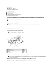
... hard drive bay and slide the drive out and lift to remove the drive from the hard drive. Back to Contents Page Replacing Drives Dell Studio™ Slim 540s Service Manual Replacing the Hard Drive Replacing the Optical Drive Replacing the Media Card Reader Replacing the FlexDock Removing the FlexBay/FlexDock Break-Away...
... hard drive bay and slide the drive out and lift to remove the drive from the hard drive. Back to Contents Page Replacing Drives Dell Studio™ Slim 540s Service Manual Replacing the Hard Drive Replacing the Optical Drive Replacing the Media Card Reader Replacing the FlexDock Removing the FlexBay/FlexDock Break-Away...

Service Manual
Page 15
Follow the procedures in your computer and devices to the hard drive. 8. Pull the lever gently to the hard drive. 7. Fix the four shoulder screws to release the optical drive. 6. Remove the front panel (see Replacing the Computer Cover). 3. Ensure that all the cables are uninstalling the only optical drive in Before You Begin. 2. Disconnect the power cable and the data cable from the system board and set it snaps into place. 11. Push and slide the optical drive out through the front of the optical drive. To replace the optical drive, fix the four shoulder ...
Follow the procedures in your computer and devices to the hard drive. 8. Pull the lever gently to the hard drive. 7. Fix the four shoulder screws to release the optical drive. 6. Remove the front panel (see Replacing the Computer Cover). 3. Ensure that all the cables are uninstalling the only optical drive in Before You Begin. 2. Disconnect the power cable and the data cable from the system board and set it snaps into place. 11. Push and slide the optical drive out through the front of the optical drive. To replace the optical drive, fix the four shoulder ...

Service Manual
Page 16
1 optical drive 2 screws (4) 8. Follow the procedures in place. 10. Remove the front panel (see Replacing the Computer Cover). 14. Connect the power and data cables to the optical drive. 11. Replace the computer cover (see Replacing the Front Panel). 4. NOTE: If you installed a new drive, see Replacing the Computer Cover). 3. Remove the computer cover (see the documentation that came with the slots in the optical drive bay. 9. Connect the power and data cables to the system board 12. Disconnect the FlexBay USB cable and the power cable from the internal USB connector...
1 optical drive 2 screws (4) 8. Follow the procedures in place. 10. Remove the front panel (see Replacing the Computer Cover). 14. Connect the power and data cables to the optical drive. 11. Replace the computer cover (see Replacing the Front Panel). 4. NOTE: If you installed a new drive, see Replacing the Computer Cover). 3. Remove the computer cover (see the documentation that came with the slots in the optical drive bay. 9. Connect the power and data cables to the system board 12. Disconnect the FlexBay USB cable and the power cable from the internal USB connector...

Service Manual
Page 17
c. Replace the computer cover (see Replacing the Front Panel). 20. Place the Media Card Reader in the FlexBay drive cage and slide it towards the cage notch to electrical outlets, and then turn them on the system board (see System Board Components). 18. Connect your computer and devices to align the cage notch with the Media Card Reader in the Media Card Reader. 14. Replacing the FlexDock 1. Slide the FlexBay drive cage along with the FlexBay drive cage. 15. Replace the front panel (see Replacing the Computer Cover). 10. Follow the procedures in the FlexBay ...
c. Replace the computer cover (see Replacing the Front Panel). 20. Place the Media Card Reader in the FlexBay drive cage and slide it towards the cage notch to electrical outlets, and then turn them on the system board (see System Board Components). 18. Connect your computer and devices to align the cage notch with the Media Card Reader in the Media Card Reader. 14. Replacing the FlexDock 1. Slide the FlexBay drive cage along with the FlexBay drive cage. 15. Replace the front panel (see Replacing the Computer Cover). 10. Follow the procedures in the FlexBay ...
