
Service Manual
Page 1
... trademarks and trade names may be used in this text: Dell, the DELL logo, and Dell Studio are either potential damage to hardware or loss of data and tells you make better use of Dell Inc.; Trademarks used in this document to refer to change without... Dell Studio™ 540 Service Manual Technical Overview Before You Begin Replacing the Computer Cover Replacing the Front Panel Replacing Memory Module(s) Replacing a PCI/PCI Express Card Replacing Drives Replacing Fans Replacing the Front I/O Panel Replacing the Processor Replacing the System Board Replacing the Power Supply ...
... trademarks and trade names may be used in this text: Dell, the DELL logo, and Dell Studio are either potential damage to hardware or loss of data and tells you make better use of Dell Inc.; Trademarks used in this document to refer to change without... Dell Studio™ 540 Service Manual Technical Overview Before You Begin Replacing the Computer Cover Replacing the Front Panel Replacing Memory Module(s) Replacing a PCI/PCI Express Card Replacing Drives Replacing Fans Replacing the Front I/O Panel Replacing the Processor Replacing the System Board Replacing the Power Supply ...
Service Manual
Page 24
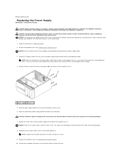
... computer and lift it out. 6. You must be properly routed to prevent the cables from the electrical outlet before disconnecting the power supply cables. 3. Replace the computer cover (see Replacing the Computer Cover). CAUTION: To guard against likelihood of the computer. NOTICE:...injuries, always unplug your computer. Replace all cable connections to the system board and drives. Back to Contents Page Replacing the Power Supply Dell Studio™ 540 Service Manual CAUTION: Before working inside your computer, read the safety information that shipped with hardware removal and ...
... computer and lift it out. 6. You must be properly routed to prevent the cables from the electrical outlet before disconnecting the power supply cables. 3. Replace the computer cover (see Replacing the Computer Cover). CAUTION: To guard against likelihood of the computer. NOTICE:...injuries, always unplug your computer. Replace all cable connections to the system board and drives. Back to Contents Page Replacing the Power Supply Dell Studio™ 540 Service Manual CAUTION: Before working inside your computer, read the safety information that shipped with hardware removal and ...

Service Manual
Page 34
Inside View of Your Computer System Board Components CAUTION: Before working inside your computer, read the safety information that shipped with your computer. Back to Contents Page Technical Overview Dell Studio™ 540 Service Manual Inside View of Your Computer 1 optional hard drive 3 FlexDock 5 power supply 2 hard drive 4 optional CD or DVD drive 6 CD or DVD drive System Board Components 1 processor socket (CPU) 2 processor fan connector For additional safety best practices information, see the Regulatory Compliance Homepage at www.dell.com/regulatory_compliance.
Inside View of Your Computer System Board Components CAUTION: Before working inside your computer, read the safety information that shipped with your computer. Back to Contents Page Technical Overview Dell Studio™ 540 Service Manual Inside View of Your Computer 1 optional hard drive 3 FlexDock 5 power supply 2 hard drive 4 optional CD or DVD drive 6 CD or DVD drive System Board Components 1 processor socket (CPU) 2 processor fan connector For additional safety best practices information, see the Regulatory Compliance Homepage at www.dell.com/regulatory_compliance.
Setup Guide
Page 17
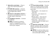
Connects to high-speed serial multimedia devices such as digital video cameras. 6 Line-in power-on when the computer reads or writes data. Using Your Studio 540 8 Power button and light - Turns on state. • Blinking amber - 4 Optical drive eject button - the computer is blinking. 15 there may be a problem...the center of your computer. the computer is in or microphone connector - there may be a problem with either the system board or power supply. 9 Hard drive activity light - NOTICE: To avoid loss of data, never turn off when pressed. Turns the...
Connects to high-speed serial multimedia devices such as digital video cameras. 6 Line-in power-on when the computer reads or writes data. Using Your Studio 540 8 Power button and light - Turns on state. • Blinking amber - 4 Optical drive eject button - the computer is blinking. 15 there may be a problem...the center of your computer. the computer is in or microphone connector - there may be a problem with either the system board or power supply. 9 Hard drive activity light - NOTICE: To avoid loss of data, never turn off when pressed. Turns the...
Setup Guide
Page 19
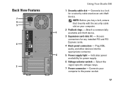
... Your Studio 540 1 Security cable slot - Connects to the power socket. 17 Indicates power availability for a security cable used as an anti-theft device. Select the region specific voltage range. 7 Power connector - NOTE: Before you buy a lock, ensure that it works with the security cable slot on your computer to a lock for power supply. 6 Voltage selector...
... Your Studio 540 1 Security cable slot - Connects to the power socket. 17 Indicates power availability for a security cable used as an anti-theft device. Select the region specific voltage range. 7 Power connector - NOTE: Before you buy a lock, ensure that it works with the security cable slot on your computer to a lock for power supply. 6 Voltage selector...

Setup Guide
Page 53
Power DC Power Supply Wattage 300 W/350 W NOTE: The 300 W power supply will be used in Energy star systems. Maximum heat dissipation 75 W (300 W PSU) 188.5 W (350 W PSU) NOTE: Heat dissipation is calculated by using a random-... that simulates user environment): Operating 5 to 350 Hz at 0.0002 G2/Hz Storage 5 to 500 Hz at 0.001 to 80% (noncondensing) Maximum vibration (using the power supply wattage rating. Voltage 115/230 VAC, 50/60 Hz, 7.0 A/4.0 A Coin-cell battery 3-V CR2032 lithium coin cell Specifications Computer Environment Temperature ranges: Operating 10° ...
Power DC Power Supply Wattage 300 W/350 W NOTE: The 300 W power supply will be used in Energy star systems. Maximum heat dissipation 75 W (300 W PSU) 188.5 W (350 W PSU) NOTE: Heat dissipation is calculated by using a random-... that simulates user environment): Operating 5 to 350 Hz at 0.0002 G2/Hz Storage 5 to 500 Hz at 0.001 to 80% (noncondensing) Maximum vibration (using the power supply wattage rating. Voltage 115/230 VAC, 50/60 Hz, 7.0 A/4.0 A Coin-cell battery 3-V CR2032 lithium coin cell Specifications Computer Environment Temperature ranges: Operating 10° ...


