
Service Manual
Page 1
Information in this text: Dell, the DELL logo, and Dell Studio are either trademarks or registered trademarks of Dell Inc. Dell Inc. Trademarks used in this document is strictly forbidden. Model: DCMA July 2008 Rev. is subject to .... Dell Studio™ 540 Service Manual Technical Overview Before You Begin Replacing the Computer Cover Replacing the Front Panel Replacing Memory Module(s) Replacing a PCI/PCI Express Card Replacing Drives Replacing Fans Replacing the Front I/O Panel Replacing the Processor Replacing the System Board Replacing the Power Supply Replacing...
Information in this text: Dell, the DELL logo, and Dell Studio are either trademarks or registered trademarks of Dell Inc. Dell Inc. Trademarks used in this document is strictly forbidden. Model: DCMA July 2008 Rev. is subject to .... Dell Studio™ 540 Service Manual Technical Overview Before You Begin Replacing the Computer Cover Replacing the Front Panel Replacing Memory Module(s) Replacing a PCI/PCI Express Card Replacing Drives Replacing Fans Replacing the Front I/O Panel Replacing the Processor Replacing the System Board Replacing the Power Supply Replacing...
Service Manual
Page 24
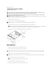
... underneath the tabs in Before You Begin. 2. Remove the computer cover (see Replacing the Computer Cover). 10. Back to Contents Page Replacing the Power Supply Dell Studio™ 540 Service Manual CAUTION: Before working inside your computer, read the safety information that shipped with hardware removal and replacement. You must be properly routed to ...
... underneath the tabs in Before You Begin. 2. Remove the computer cover (see Replacing the Computer Cover). 10. Back to Contents Page Replacing the Power Supply Dell Studio™ 540 Service Manual CAUTION: Before working inside your computer, read the safety information that shipped with hardware removal and replacement. You must be properly routed to ...

Service Manual
Page 34
Inside View of Your Computer System Board Components CAUTION: Before working inside your computer, read the safety information that shipped with your computer. Back to Contents Page Technical Overview Dell Studio™ 540 Service Manual Inside View of Your Computer 1 optional hard drive 3 FlexDock 5 power supply 2 hard drive 4 optional CD or DVD drive 6 CD or DVD drive System Board Components 1 processor socket (CPU) 2 processor fan connector For additional safety best practices information, see the Regulatory Compliance Homepage at www.dell.com/regulatory_compliance.
Inside View of Your Computer System Board Components CAUTION: Before working inside your computer, read the safety information that shipped with your computer. Back to Contents Page Technical Overview Dell Studio™ 540 Service Manual Inside View of Your Computer 1 optional hard drive 3 FlexDock 5 power supply 2 hard drive 4 optional CD or DVD drive 6 CD or DVD drive System Board Components 1 processor socket (CPU) 2 processor fan connector For additional safety best practices information, see the Regulatory Compliance Homepage at www.dell.com/regulatory_compliance.
Setup Guide
Page 17
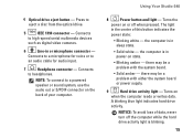
... sound system, use the audio out or S/PDIF connector on or off the computer while the hard drive activity light is blinking. 15 Using Your Studio 540 8 Power button and light - Connects to eject a disc from the optical drive. 5 IEEE 1394 connector - The light in or microphone connector - A ... amber - Press to headphones. Connects to a microphone for audio input. 7 Headphone connector - there may be a problem with either the system board or power supply. 9 Hard drive activity light - the computer is in sleep state. • Solid white -
... sound system, use the audio out or S/PDIF connector on or off the computer while the hard drive activity light is blinking. 15 Using Your Studio 540 8 Power button and light - Connects to eject a disc from the optical drive. 5 IEEE 1394 connector - The light in or microphone connector - A ... amber - Press to headphones. Connects to a microphone for audio input. 7 Headphone connector - there may be a problem with either the system board or power supply. 9 Hard drive activity light - the computer is in sleep state. • Solid white -
Setup Guide
Page 19
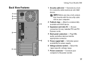
... 1 available anti-theft device. 3 Expansion card slots (4) - Access connectors for power supply. 6 Voltage selector switch - Connects your computer. 2 Padlock rings - Connects to the power socket. 17 NOTE: Before you buy a lock, ensure that it works with ... specific voltage range. 7 Power connector - Indicates power availability for any installed PCI and PCI Express cards. 4 Back panel connectors - Plug USB, audio, and other devices into the appropriate connector. 2 5 Power supply light - Back View Features 7 6 5 4 3 Using Your Studio 540 1 Security cable slot -...
... 1 available anti-theft device. 3 Expansion card slots (4) - Access connectors for power supply. 6 Voltage selector switch - Connects your computer. 2 Padlock rings - Connects to the power socket. 17 NOTE: Before you buy a lock, ensure that it works with ... specific voltage range. 7 Power connector - Indicates power availability for any installed PCI and PCI Express cards. 4 Back panel connectors - Plug USB, audio, and other devices into the appropriate connector. 2 5 Power supply light - Back View Features 7 6 5 4 3 Using Your Studio 540 1 Security cable slot -...


