Service Manual
Page 7
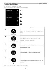
... the buttons on the front of the monitor to adjust the image settings. 20" LCD Color Monitor 3. Dell SP2009Wc Front panel Button A Preset modes B Description Use the Preset modes button to adjust the image settings. 7 C Use the Input source button to select different video signals that may be connected to the "Brightness" and "Contrast" control...
... the buttons on the front of the monitor to adjust the image settings. 20" LCD Color Monitor 3. Dell SP2009Wc Front panel Button A Preset modes B Description Use the Preset modes button to adjust the image settings. 7 C Use the Input source button to select different video signals that may be connected to the "Brightness" and "Contrast" control...
Service Manual
Page 11
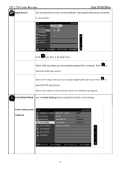
.... COLOR SETTINGS Use the Color Setting menu to your monitor. Select DVI-D input when you are using the analog (VGA) connector. 20" LCD Color Monitor Dell SP2009Wc Input Source Use the Input Source menu to select different video signals that may be connected to adjust the monitor's color settings. Select Auto select to the main menu...
.... COLOR SETTINGS Use the Color Setting menu to your monitor. Select DVI-D input when you are using the analog (VGA) connector. 20" LCD Color Monitor Dell SP2009Wc Input Source Use the Input Source menu to select different video signals that may be connected to adjust the monitor's color settings. Select Auto select to the main menu...
Service Manual
Page 12
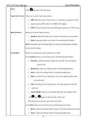
... select the Preset Modes available for movies. In the Video mode, you can set the display mode to: • Graphics: Select this mode if your monitor is connected to your computer. • Video: Select this mode if you to set the color to a DVD player. Mode Selection Allows you...; RGB: Select this option if the your DVD player supports only YPbPr output. 20" LCD Color Monitor Back Press to go back to adjust the Red, Green, and Blue values and create your own preset color mode. Dell SP2009Wc Input Color Format Allows you can set the video input mode to choose from...
... select the Preset Modes available for movies. In the Video mode, you can set the display mode to: • Graphics: Select this mode if your monitor is connected to your computer. • Video: Select this mode if you to set the color to a DVD player. Mode Selection Allows you...; RGB: Select this option if the your DVD player supports only YPbPr output. 20" LCD Color Monitor Back Press to go back to adjust the Red, Green, and Blue values and create your own preset color mode. Dell SP2009Wc Input Color Format Allows you can set the video input mode to choose from...
Service Manual
Page 26
...the power key pressed? 26 Scalar initializes. 10) In standby mode? 11) Update the lifetime of brightness from analog port? 16) Display "No connection Check Signal Cable" message. And go into EEprom. Turn on the LED and set it to show the coming from EEprom. 5) Is the power... 9) Save the power key status into standby mode after the message disappears. 17) Program the scalar to be able to green color. 20" LCD Color Monitor 1) MCU Initializes. Dell SP2009Wc 2) Is the EEprom blank? 3) Program the EEprom by default values. 4) Get the PWM value of back light. 12) Check the analog...
...the power key pressed? 26 Scalar initializes. 10) In standby mode? 11) Update the lifetime of brightness from analog port? 16) Display "No connection Check Signal Cable" message. And go into EEprom. Turn on the LED and set it to show the coming from EEprom. 5) Is the power... 9) Save the power key status into standby mode after the message disappears. 17) Program the scalar to be able to green color. 20" LCD Color Monitor 1) MCU Initializes. Dell SP2009Wc 2) Is the EEprom blank? 3) Program the EEprom by default values. 4) Get the PWM value of back light. 12) Check the analog...

Service Manual
Page 33
... as shown Fig 2 ,it means NG, otherwise means Ok. The monitor enter pending request. 20" LCD Color Monitor Camera & Microphone test sop Preparation: open PC, Double click SP2009Cameratest Dell SP2009Wc and adsrecorder Step:1.connect monitor USB ports bring up in Fig.1 and PC USB ports with USB ...cable Monitor USB ports Fig 1 Step2:when appear picture in test window ...
... as shown Fig 2 ,it means NG, otherwise means Ok. The monitor enter pending request. 20" LCD Color Monitor Camera & Microphone test sop Preparation: open PC, Double click SP2009Cameratest Dell SP2009Wc and adsrecorder Step:1.connect monitor USB ports bring up in Fig.1 and PC USB ports with USB ...cable Monitor USB ports Fig 1 Step2:when appear picture in test window ...

Service Manual
Page 54
20" LCD Color Monitor No Backlight Check CN902 pin7, 8 = 5V OK NG Check ON/OFF signal OK NG Check IC801 PIN12=13V Dell SP2009Wc Check adapter or MB Check Interface board NG OK Change Q802, Q803 Check IC801 PIN10, 9 have the output of square wave at short time NG OK Change IC801 Check Q803,Q802 PIN5, 6, 7, 8 have the output of T801,T802 NG OK Check connecter & lamp Change T801,T802 54 NG Check Q802, Q803,D810, D812, Q801 ,Q804,Q811andQ812 OK Check the output of square wave at short time.
20" LCD Color Monitor No Backlight Check CN902 pin7, 8 = 5V OK NG Check ON/OFF signal OK NG Check IC801 PIN12=13V Dell SP2009Wc Check adapter or MB Check Interface board NG OK Change Q802, Q803 Check IC801 PIN10, 9 have the output of square wave at short time NG OK Change IC801 Check Q803,Q802 PIN5, 6, 7, 8 have the output of T801,T802 NG OK Check connecter & lamp Change T801,T802 54 NG Check Q802, Q803,D810, D812, Q801 ,Q804,Q811andQ812 OK Check the output of square wave at short time.
Service Manual
Page 55
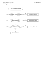
Y Is Button Switch normally? Y Is Key Pad Board normally? Y Check Main Board N Connect Key Pad Board N Replace Button Switch N Replace Key Pad Board 55 20" LCD Color Monitor 9.2.3 Key Board OSD is unstable or not working Dell SP2009Wc Is Key Pad Board connecting normally?
Y Is Button Switch normally? Y Is Key Pad Board normally? Y Check Main Board N Connect Key Pad Board N Replace Button Switch N Replace Key Pad Board 55 20" LCD Color Monitor 9.2.3 Key Board OSD is unstable or not working Dell SP2009Wc Is Key Pad Board connecting normally?

Service Manual
Page 58
Update the firmware Step 1: Double click the ISP_Tool v3.772.exe icon and click Connect, bring up Fig.2 Fig.2 58 Microsoft operation system Window 95/98/2000/XP. (3). System and equipment requirements (1). ISP Tool: ISP board/printer cable/VGA cable as shown in MS-DOS. An i486 (or above) personal computer or computer or compatible. (2). ISP Instruction Configure and procedure It is a windows-based program, which cannot be run in Fig.1 Dell SP2009Wc Link to Dell VGA connector Connect to PC LPT (4). 20" LCD Color Monitor 11. ISP software checklist Fig.1 (5).
Update the firmware Step 1: Double click the ISP_Tool v3.772.exe icon and click Connect, bring up Fig.2 Fig.2 58 Microsoft operation system Window 95/98/2000/XP. (3). System and equipment requirements (1). ISP Tool: ISP board/printer cable/VGA cable as shown in MS-DOS. An i486 (or above) personal computer or computer or compatible. (2). ISP Instruction Configure and procedure It is a windows-based program, which cannot be run in Fig.1 Dell SP2009Wc Link to Dell VGA connector Connect to PC LPT (4). 20" LCD Color Monitor 11. ISP software checklist Fig.1 (5).


