
Dell Networking Getting Started Guide
Page 5
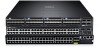
... Hardware installation and power-up and running and ready for configuration. It is available on the Dell Support website at http://www.dell.com/support/manuals. The S5000 supports Data Center Bridging (ETS/PFC/DCBX), FCoE Transit (FIP Snooping), NPIV Proxy Gateway (NPG...form factor. The S5000 delivers Fibre Channel over Ethernet (FCoE) and Fibre Channel (FC) capability in the same box. The S5000 also provides aggregation and convergence functionality using pluggable modules for flexible configuration. 3 Getting Started Guide This document is part of Dell Networking's S-Series ...
... Hardware installation and power-up and running and ready for configuration. It is available on the Dell Support website at http://www.dell.com/support/manuals. The S5000 supports Data Center Bridging (ETS/PFC/DCBX), FCoE Transit (FIP Snooping), NPIV Proxy Gateway (NPG...form factor. The S5000 delivers Fibre Channel over Ethernet (FCoE) and Fibre Channel (FC) capability in the same box. The S5000 also provides aggregation and convergence functionality using pluggable modules for flexible configuration. 3 Getting Started Guide This document is part of Dell Networking's S-Series ...
Dell Networking Getting Started Guide
Page 6
...your Dell Networking representative or reseller for instructions. Important Points Before You Continue • Identify the I/O and Utility panel on the right side of damage. The Utility panel has 4 Always wear an ESD-preventive wrist or heel ground strap when handling the S5000 and ...its accessories are shipped in multiple boxes. Open the container or remove the container top. 3. WARNING: Electrostatic discharge (ESD) damage can occur if components are included. The I /O Modules (according to order) • Two Blanks ...
...your Dell Networking representative or reseller for instructions. Important Points Before You Continue • Identify the I/O and Utility panel on the right side of damage. The Utility panel has 4 Always wear an ESD-preventive wrist or heel ground strap when handling the S5000 and ...its accessories are shipped in multiple boxes. Open the container or remove the container top. 3. WARNING: Electrostatic discharge (ESD) damage can occur if components are included. The I /O Modules (according to order) • Two Blanks ...
Dell Networking Getting Started Guide
Page 7
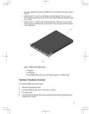
...the left side of the slots. Utility panel 3. You can insert a Fibre Channel module only in slots 0 and 3. Attach the mounting brackets. 2. Install the S5000 chassis into a 4-post rack or cabinet. 3. S5000 I /O panel 2. Four 40GbE QSFP+ ports (each port ALSO supports 4 ×...; 10GbE mode) Hardware Installation Overview To install the S5000, follow these steps: 1. You can insert Power supply units (PSUs) only in slot 0. I /O and Utility Panels 1. Install the Ethernet and/or Fibre Channel modules (Fibre Channel module must be installed only in slots 0, 1, 2, and 3. &#...
...the left side of the slots. Utility panel 3. You can insert a Fibre Channel module only in slots 0 and 3. Attach the mounting brackets. 2. Install the S5000 chassis into a 4-post rack or cabinet. 3. S5000 I /O panel 2. Four 40GbE QSFP+ ports (each port ALSO supports 4 ×...; 10GbE mode) Hardware Installation Overview To install the S5000, follow these steps: 1. You can insert Power supply units (PSUs) only in slot 0. I /O and Utility Panels 1. Install the Ethernet and/or Fibre Channel modules (Fibre Channel module must be installed only in slots 0, 1, 2, and 3. &#...
Dell Networking Getting Started Guide
Page 8
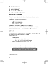
...includes: • Pluggable Modules - 12-Port Ethernet Module (1G/10G speeds) - 12-Port Fibre Channel Module (2G/4G/8G speeds) • 4 × 40GbE QSFP+ Ports and light emitting diodes (LEDs) Figure 2. The I /O panel. Install the SFP+ and QSFP+ optics. 9. S5000 I/O Panel 6 The S5000 has the following physical ...dedicated Ethernet service port for the S5000. Supply power and power up the system. 5. Install the power supplies. 6. The system also provides one DB9 RS-232 console port with 640Gbps switching bandwidth. Install the fan modules. 8. Hardware Overview This section ...
...includes: • Pluggable Modules - 12-Port Ethernet Module (1G/10G speeds) - 12-Port Fibre Channel Module (2G/4G/8G speeds) • 4 × 40GbE QSFP+ Ports and light emitting diodes (LEDs) Figure 2. The I /O panel. Install the SFP+ and QSFP+ optics. 9. S5000 I/O Panel 6 The S5000 has the following physical ...dedicated Ethernet service port for the S5000. Supply power and power up the system. 5. Install the power supplies. 6. The system also provides one DB9 RS-232 console port with 640Gbps switching bandwidth. Install the fan modules. 8. Hardware Overview This section ...

Dell Networking Getting Started Guide
Page 9
...) NOTE: The LED displays for the system status are on the Utility panel. S5000 Power Supplies and Fan Modules 1. Slot 3 (supports only Ethernet modules) 5. Grab Handles Power Supplies The S5000 supports two hot-swappable PSUs. When running with fan airflow from I/O to I/O...power status LEDs are field replaceable. Slot 1 (for PSU 1) 5. Slot 1 (supports only Ethernet modules) 3. Slot 3 (for Fan Module 0) 3. Slot 0 (supports Ethernet and Fibre Channel modules) 2. The S5000 has SKUs that support the following configurations: • AC PSU with fan airflow from I/O to ...
...) NOTE: The LED displays for the system status are on the Utility panel. S5000 Power Supplies and Fan Modules 1. Slot 3 (supports only Ethernet modules) 5. Grab Handles Power Supplies The S5000 supports two hot-swappable PSUs. When running with fan airflow from I/O to I/O...power status LEDs are field replaceable. Slot 1 (for PSU 1) 5. Slot 1 (supports only Ethernet modules) 3. Slot 3 (for Fan Module 0) 3. Slot 0 (supports Ethernet and Fibre Channel modules) 2. The S5000 has SKUs that support the following configurations: • AC PSU with fan airflow from I/O to ...
Dell Networking Getting Started Guide
Page 10
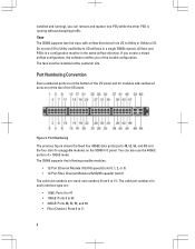
...remove and replace one PSU while the other PSU is running without disrupting traffic. The S5000 supports the following possible modules: • 12-Port Ethernet Module (1G/10G speeds) (slot 0, 1, 2, or 3) • 12-Port Fibre Channel Module (2G/4G/8G speeds) (slot 0) The valid slot numbers are : •... Channel: Ports 0 to I /O airflows in a single S5000 chassis. All fans and PSUs in a configuration must be in 4 × 10GbE mode. Port Numbering Convention Even-numbered ports are at the bottom of the I/O panel and for modules odd-numbered ports are at the customer site. Figure 4....
...remove and replace one PSU while the other PSU is running without disrupting traffic. The S5000 supports the following possible modules: • 12-Port Ethernet Module (1G/10G speeds) (slot 0, 1, 2, or 3) • 12-Port Fibre Channel Module (2G/4G/8G speeds) (slot 0) The valid slot numbers are : •... Channel: Ports 0 to I /O airflows in a single S5000 chassis. All fans and PSUs in a configuration must be in 4 × 10GbE mode. Port Numbering Convention Even-numbered ports are at the bottom of the I/O panel and for modules odd-numbered ports are at the customer site. Figure 4....

Dell Networking Getting Started Guide
Page 13
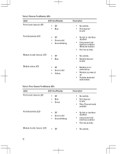
Port link/activity LED 3. Module status LED NOTE: The downward and upward pointing triangles denote the lower and upper port LEDs respectively. 11 Port locator beacon LED 2. Module locator beacon LED 4. Label PSU status LED Fan status LED LED Color/Display • Green solid • Off • Green solid • Off Description • Switch in Stacking Member mode • Normal operation • Power not present • Normal operation • Power not present Figure 7. Module LEDs 1.
Port link/activity LED 3. Module status LED NOTE: The downward and upward pointing triangles denote the lower and upper port LEDs respectively. 11 Port locator beacon LED 2. Module locator beacon LED 4. Label PSU status LED Fan status LED LED Color/Display • Green solid • Off • Green solid • Off Description • Switch in Stacking Member mode • Normal operation • Power not present • Normal operation • Power not present Figure 7. Module LEDs 1.
Dell Networking Getting Started Guide
Page 14
...Port locator beacon LED • Off • Blue • Green Port link/activity LED • Off • Green solid • Green blinking Module locator beacon LED • Off Description • No activity • Port beacon/ locator • No link or interface disabled • Link present ... • No link or interface disabled • Link present and interface enabled • Port has activity • No activity 12 Ethernet Port/Module LEDs Label LED Color/Display Port locator beacon LED • Off • Blue Port link/activity LED • Off • Green solid ...
...Port locator beacon LED • Off • Blue • Green Port link/activity LED • Off • Green solid • Green blinking Module locator beacon LED • Off Description • No activity • Port beacon/ locator • No link or interface disabled • Link present ... • No link or interface disabled • Link present and interface enabled • Port has activity • No activity 12 Ethernet Port/Module LEDs Label LED Color/Display Port locator beacon LED • Off • Blue Port link/activity LED • Off • Green solid ...
Dell Networking Getting Started Guide
Page 15
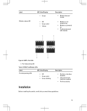
QSFP+ Port LEDs 1. Port link/activity LED Table 5. 40GbE Port/Module LEDs Label LED Color/Display Port link/activity LED • Off • Green solid • Green blinking Description • No link or interface disabled • ...Link present and interface enabled • Port has activity Installation Before installing the switch, verify that you meet these guidelines: 13 Label Module status LED LED Color/Display • Green • Off • Green solid • Yellow Description •...
QSFP+ Port LEDs 1. Port link/activity LED Table 5. 40GbE Port/Module LEDs Label LED Color/Display Port link/activity LED • Off • Green solid • Green blinking Description • No link or interface disabled • ...Link present and interface enabled • Port has activity Installation Before installing the switch, verify that you meet these guidelines: 13 Label Module status LED LED Color/Display • Green • Off • Green solid • Yellow Description •...
Dell Networking Getting Started Guide
Page 16
...cord reaches from the power outlet to the Utility-panel connector. • Switch is rack-mounted before you install the power supply modules. • Cabling is away from sources of electrical noise, such as metal flakes from construction activities). Cooling mechanisms, such as...in a closed or multirack assembly, the temperature might damage the cables. As with care. Install the S5000 Chassis in a Rack or Cabinet To install the S5000 system, Dell Networking recommends completing the installation procedures in system malfunction. NOTE: Always handle the system and its components with...
...cord reaches from the power outlet to the Utility-panel connector. • Switch is rack-mounted before you install the power supply modules. • Cabling is away from sources of electrical noise, such as metal flakes from construction activities). Cooling mechanisms, such as...in a closed or multirack assembly, the temperature might damage the cables. As with care. Install the S5000 Chassis in a Rack or Cabinet To install the S5000 system, Dell Networking recommends completing the installation procedures in system malfunction. NOTE: Always handle the system and its components with...

Dell Networking Getting Started Guide
Page 19
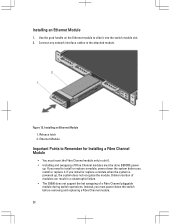
The ground path must be done BEFORE power up , the system does not recognize the module. If you install or replace a module when the system is earth ground. Online insertion of Ethernet modules must ground the equipment rack to the same ground point the power service uses in a ... replace it. You must be permanent. Figure 10. Front Rack Installation 1. If you need to Remember for Installing an Ethernet Module • Installing and swapping of modules can result in your equipment rack, ensure that the rack is powered up . Screws 2. 4-Post Rack or Cabinet 3. Important...
The ground path must be done BEFORE power up , the system does not recognize the module. If you install or replace a module when the system is earth ground. Online insertion of Ethernet modules must ground the equipment rack to the same ground point the power service uses in a ... replace it. You must be permanent. Figure 10. Front Rack Installation 1. If you need to Remember for Installing an Ethernet Module • Installing and swapping of modules can result in your equipment rack, ensure that the rack is powered up . Screws 2. 4-Post Rack or Cabinet 3. Important...
Dell Networking Getting Started Guide
Page 20
WARNING: Electrostatic discharge (ESD) damage can occur if components are inscribed on the handle, as shown in the following figure: 18 Always wear an ESD-preventive wrist or heel ground strap when handling the S5000 and its components. NOTE: For the Ethernet module, the part name and port number are mishandled.
WARNING: Electrostatic discharge (ESD) damage can occur if components are inscribed on the handle, as shown in the following figure: 18 Always wear an ESD-preventive wrist or heel ground strap when handling the S5000 and its components. NOTE: For the Ethernet module, the part name and port number are mishandled.

Dell Networking Getting Started Guide
Page 21
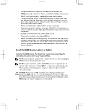
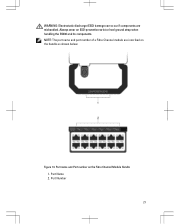
Part name and Port number on the Ethernet Module Handle 1. Figure 11. Port Number 19 A red color release latch indicates that the Ethernet module does not support hot swapping during switch operations. Part Name 2. NOTE: A blue color release latch indicates that the Ethernet module supports hot swapping during switch operations. Instead, you must power down the switch before removing and replacing an Ethernet module.
Part name and Port number on the Ethernet Module Handle 1. Figure 11. Port Number 19 A red color release latch indicates that the Ethernet module does not support hot swapping during switch operations. Part Name 2. NOTE: A blue color release latch indicates that the Ethernet module supports hot swapping during switch operations. Instead, you must power down the switch before removing and replacing an Ethernet module.
Dell Networking Getting Started Guide
Page 22
... for Installing a Fibre Channel Module • You must insert the Fibre Channel module only in a catastrophic failure. • The S5000 does not support the hot swapping of Fibre Channel modules must power down the system before removing and replacing a Fibre Channel module. 20 Ethernet Module Important Points to install or replace a module, power down the switch before...
... for Installing a Fibre Channel Module • You must insert the Fibre Channel module only in a catastrophic failure. • The S5000 does not support the hot swapping of Fibre Channel modules must power down the system before removing and replacing a Fibre Channel module. 20 Ethernet Module Important Points to install or replace a module, power down the switch before...
Dell Networking Getting Started Guide
Page 23
Always wear an ESD-preventive wrist or heel ground strap when handling the S5000 and its components. Port Number 21 Figure 13. Part name and Port number on the handle as shown below. Part Name 2. WARNING: Electrostatic discharge (ESD) damage can occur if components are inscribed on the Fibre Channel Module Handle 1. NOTE: The part name and port number of a Fibre Channel module are mishandled.
Always wear an ESD-preventive wrist or heel ground strap when handling the S5000 and its components. Port Number 21 Figure 13. Part name and Port number on the handle as shown below. Part Name 2. WARNING: Electrostatic discharge (ESD) damage can occur if components are inscribed on the Fibre Channel Module Handle 1. NOTE: The part name and port number of a Fibre Channel module are mishandled.
Dell Networking Getting Started Guide
Page 24
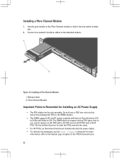
...fan airflow direction for Installing an AC Power Supply • The PSU slides into a slot as this action may damage the PSU or the S5000 chassis. • The S5000 supports AC and DC power supplies with a DC-R PSU. Figure 14. Do not force a PSU into the slot smoothly. Installing a Fibre... Channel Module 1. Release latch 2. Fibre Channel Module Important Points to Remember for both the PSUs must be the same. • For AC PSUs, an ...
...fan airflow direction for Installing an AC Power Supply • The PSU slides into a slot as this action may damage the PSU or the S5000 chassis. • The S5000 supports AC and DC power supplies with a DC-R PSU. Figure 14. Do not force a PSU into the slot smoothly. Installing a Fibre... Channel Module 1. Release latch 2. Fibre Channel Module Important Points to Remember for both the PSUs must be the same. • For AC PSUs, an ...
Dell Networking Getting Started Guide
Page 32
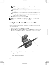
... supply slots. Installing the Ferrite Bead for DC Power and Return Cables Add a ferrite bead to the DC power and return cables of the master module. Ferrite Bead 2. DC Power and Return Cables 30 CAUTION: Use the power supply cord as the power cord is connected between the system and the...
... supply slots. Installing the Ferrite Bead for DC Power and Return Cables Add a ferrite bead to the DC power and return cables of the master module. Ferrite Bead 2. DC Power and Return Cables 30 CAUTION: Use the power supply cord as the power cord is connected between the system and the...
Dell Networking Getting Started Guide
Page 33
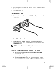
..., and attach to the cable clasp. Securing Power Cables 1. Important Points to 3. Bend the system power cables, as shown in cooling capacity for Installing a Fan Module • The Utility panel consists of the power cables into a grounded electrical outlet or a separate power source such as an uninterruptible power supply (UPS) or...
..., and attach to the cable clasp. Securing Power Cables 1. Important Points to 3. Bend the system power cables, as shown in cooling capacity for Installing a Fan Module • The Utility panel consists of the power cables into a grounded electrical outlet or a separate power source such as an uninterruptible power supply (UPS) or...
Dell Networking Getting Started Guide
Page 34
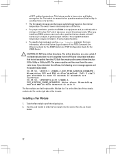
... off the fans. • For proper ventilation, position the S5000 in unit 0 The fan modules are field replaceable. When you mismatch the airflows, the following error message appears and the system shuts down: 00:00:53: %S5000:3 %CHMGR-2-PSU_TYPE_AIRFLOW_MISMATCH: Mismatching PSU and FAN airflow detected. For ...of 5 inches (12.7 cm) of the FTOS Command Line Reference Guide for the S5000 Switch and FTOS Configuration Guide for the S5000 Switch. Installing a Fan Module 1. Use the grab handle to slide the fan module into the switch fan slot, as shown below. 32 CAUTION: DO NOT mix ...
... off the fans. • For proper ventilation, position the S5000 in unit 0 The fan modules are field replaceable. When you mismatch the airflows, the following error message appears and the system shuts down: 00:00:53: %S5000:3 %CHMGR-2-PSU_TYPE_AIRFLOW_MISMATCH: Mismatching PSU and FAN airflow detected. For ...of 5 inches (12.7 cm) of the FTOS Command Line Reference Guide for the S5000 Switch and FTOS Configuration Guide for the S5000 Switch. Installing a Fan Module 1. Use the grab handle to slide the fan module into the switch fan slot, as shown below. 32 CAUTION: DO NOT mix ...
Dell Networking Getting Started Guide
Page 35
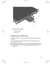
For a list of supported optics, refer to the S5000 data sheet: http://www.dell.com/us/ enterprise/p/force10-s-series/pd. Always wear an ESD-preventive wrist or heel ground strap when handling the S5000 and its components. 33 Installing a Fan Module 1. Release latch Installing the SFP+ and QSFP+ Optics The S5000 has 48 small form-factor pluggable plus (SFP+) optical ports and four QSFP+ optical ports. Fan module 0/Slot 1 2. CAUTION: ESD damage can occur if the components are mishandled. Figure 22.
For a list of supported optics, refer to the S5000 data sheet: http://www.dell.com/us/ enterprise/p/force10-s-series/pd. Always wear an ESD-preventive wrist or heel ground strap when handling the S5000 and its components. 33 Installing a Fan Module 1. Release latch Installing the SFP+ and QSFP+ Optics The S5000 has 48 small form-factor pluggable plus (SFP+) optical ports and four QSFP+ optical ports. Fan module 0/Slot 1 2. CAUTION: ESD damage can occur if the components are mishandled. Figure 22.


