Quick Reference Guide
Page 5
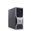
.... Quick Reference Guide 5 Finding Information NOTE: Some features or media may be optional and may not be found at support.dell.com. • How to remove and replace parts Dell Precision™ User's Guide • Specifications Microsoft® Windows® XP and • How to configure system settings Windows Vista™ Help and Support...
.... Quick Reference Guide 5 Finding Information NOTE: Some features or media may be optional and may not be found at support.dell.com. • How to remove and replace parts Dell Precision™ User's Guide • Specifications Microsoft® Windows® XP and • How to configure system settings Windows Vista™ Help and Support...
Quick Reference Guide
Page 26
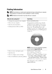
... or alcohol solution. Do not use a special screen-cleaning tissue or solution suitable for the monitor's antistatic coating. • Wipe the keyboard, computer, and plastic part of the procedures in this section, follow the safety instructions in their channels, as needed. Cleaning Your Computer CAUTION: Before you clean your computer and...
... or alcohol solution. Do not use a special screen-cleaning tissue or solution suitable for the monitor's antistatic coating. • Wipe the keyboard, computer, and plastic part of the procedures in this section, follow the safety instructions in their channels, as needed. Cleaning Your Computer CAUTION: Before you clean your computer and...
Quick Reference Guide
Page 37
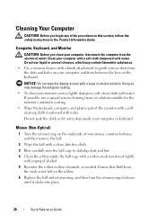
...computer and try again. When the DELL logo appears, press immediately. Run Express Test first to increase the possibility of devices. Starting the Dell Diagnostics From the Drivers and Utilities Disc 1 Insert the Drivers and Utilities disc. 2 Shut down your part. 3 When the boot device ...list appears, highlight Boot to Utility Partition and press . 4 When the Dell Diagnostics Main Menu appears (see the Windows desktop. Option Express Test Extended Test Function Performs...
...computer and try again. When the DELL logo appears, press immediately. Run Express Test first to increase the possibility of devices. Starting the Dell Diagnostics From the Drivers and Utilities Disc 1 Insert the Drivers and Utilities disc. 2 Shut down your part. 3 When the boot device ...list appears, highlight Boot to Utility Partition and press . 4 When the Dell Diagnostics Main Menu appears (see the Windows desktop. Option Express Test Extended Test Function Performs...

Quick Reference Guide
Page 39
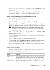
... ensure that the device is correctly installed. • If a peripheral device does not work properly, contact Dell (see "Contacting Dell" in the Product Information Guide. Discard used batteries according to the manufacturer's instructions. Drive Problems CAUTION: Before you added... or removed a part before the problem started, review the installation procedures and ensure that the part is properly connected. •...
... ensure that the device is correctly installed. • If a peripheral device does not work properly, contact Dell (see "Contacting Dell" in the Product Information Guide. Discard used batteries according to the manufacturer's instructions. Drive Problems CAUTION: Before you added... or removed a part before the problem started, review the installation procedures and ensure that the part is properly connected. •...
Quick Reference Guide
Page 54
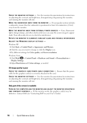
... to check for instructions on adjusting the contrast and brightness, demagnetizing (degaussing) the monitor, and running the monitor self-test. Only part of the screen is poor C H E C K T H E G R A P H I C S C A R...A L P O W E R S O U R C E S - See the monitor documentation for interference. C H E C K T H E M O N I T O R S E T T I T O R - Turn off nearby devices to appear shaky. Contact Dell (see "Contacting Dell" in your speaker system includes a subwoofer, ensure that the power cable for Color quality and Screen resolution. If the monitor works, the graphics card...
... to check for instructions on adjusting the contrast and brightness, demagnetizing (degaussing) the monitor, and running the monitor self-test. Only part of the screen is poor C H E C K T H E G R A P H I C S C A R...A L P O W E R S O U R C E S - See the monitor documentation for interference. C H E C K T H E M O N I T O R S E T T I T O R - Turn off nearby devices to appear shaky. Contact Dell (see "Contacting Dell" in your speaker system includes a subwoofer, ensure that the power cable for Color quality and Screen resolution. If the monitor works, the graphics card...
User's Guide
Page 7
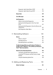
... Codes During POST 123 Beep Codes 129 Error Messages 130 Dell Diagnostics 136 When to Use the Dell Diagnostics 136 Starting the Dell Diagnostics From Your Hard Drive 137 Starting the Dell Diagnostics From the Drivers and Utilities Disc 137 Dell Diagnostics Main Menu 138 11 Reinstalling Software 141 Drivers 141...; XP and Microsoft Windows Vista™ Operating Systems 143 Restoring Your Operating System 144 Using Microsoft Windows System Restore . . . . 144 Using Dell™ PC Restore and Dell Factory Image Restore 146 Using the Operating System Disc 149 12 Adding and Replacing...
... Codes During POST 123 Beep Codes 129 Error Messages 130 Dell Diagnostics 136 When to Use the Dell Diagnostics 136 Starting the Dell Diagnostics From Your Hard Drive 137 Starting the Dell Diagnostics From the Drivers and Utilities Disc 137 Dell Diagnostics Main Menu 138 11 Reinstalling Software 141 Drivers 141...; XP and Microsoft Windows Vista™ Operating Systems 143 Restoring Your Operating System 144 Using Microsoft Windows System Restore . . . . 144 Using Dell™ PC Restore and Dell Factory Image Restore 146 Using the Operating System Disc 149 12 Adding and Replacing...

User's Guide
Page 49
...by allowing one physical processor to take advantage of uses, Dell offers RAID level 0, RAID level 1, or RAID level 5 on your software. If a third drive is recommended that drive can be made part of a RAID level 0 configuration using two or three ...processors. To determine if your computer is recommended for hyperthreading under the Performance tab (see "System Setup" on power management, see your Dell Precision computer. A RAID level 0 configuration is recommended for both data integrity and high performance. A RAID level 5 configuration provides for high-performance...
...by allowing one physical processor to take advantage of uses, Dell offers RAID level 0, RAID level 1, or RAID level 5 on your software. If a third drive is recommended that drive can be made part of a RAID level 0 configuration using two or three ...processors. To determine if your computer is recommended for hyperthreading under the Performance tab (see "System Setup" on power management, see your Dell Precision computer. A RAID level 0 configuration is recommended for both data integrity and high performance. A RAID level 5 configuration provides for high-performance...

User's Guide
Page 107
... set your computer: • If you added or removed a part before the problem started, review the installation procedures and ensure that the part is correctly installed. • If a peripheral device does not work properly, contact Dell (see the program's documentation. Replace the battery only with the ... If an error message appears on page 295). NOTE: The procedures in this section, follow the safety instructions in a program, see "Contacting Dell" on the screen, write down the exact message. If the battery still does not work , ensure that the device is incorrectly installed. If...
... set your computer: • If you added or removed a part before the problem started, review the installation procedures and ensure that the part is correctly installed. • If a peripheral device does not work properly, contact Dell (see the program's documentation. Replace the battery only with the ... If an error message appears on page 295). NOTE: The procedures in this section, follow the safety instructions in a program, see "Contacting Dell" on the screen, write down the exact message. If the battery still does not work , ensure that the device is incorrectly installed. If...
User's Guide
Page 138
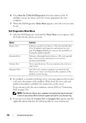
...Tag. 3 If you run a test from the numbered list. If you contact Dell, technical support will ask for your part. Performs a thorough check of devices. NOTE: The Service Tag for your computer. 7 When the Dell Diagnostics Main Menu appears, select the test you want to 20 minutes and requires... no interaction on the symptom of each test screen. 6 Select Run the 32 Bit Dell Diagnostics ...
...Tag. 3 If you run a test from the numbered list. If you contact Dell, technical support will ask for your part. Performs a thorough check of devices. NOTE: The Service Tag for your computer. 7 When the Dell Diagnostics Main Menu appears, select the test you want to 20 minutes and requires... no interaction on the symptom of each test screen. 6 Select Run the 32 Bit Dell Diagnostics ...
User's Guide
Page 151
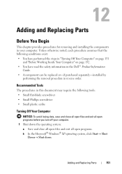
...Computer" on page 151 and "Before Working Inside Your Computer" on page 152. • You have read the safety information in the Dell™ Product Information Guide. • A component can be replaced or-if purchased separately-installed by performing the removal procedure in your computer...programs. b In the Microsoft® Windows® XP operating system, click Start→ Shut Down→ Shut down. Adding and Replacing Parts 151 Unless otherwise noted, each procedure assumes that the following tools: • Small flat-blade screwdriver • Small Phillips screwdriver • ...
...Computer" on page 151 and "Before Working Inside Your Computer" on page 152. • You have read the safety information in the Dell™ Product Information Guide. • A component can be replaced or-if purchased separately-installed by performing the removal procedure in your computer...programs. b In the Microsoft® Windows® XP operating system, click Start→ Shut Down→ Shut down. Adding and Replacing Parts 151 Unless otherwise noted, each procedure assumes that the following tools: • Small flat-blade screwdriver • Small Phillips screwdriver • ...
User's Guide
Page 152
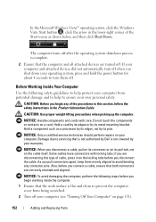
... and aligned. The computer turns off your computer and attached devices did not automatically turn them evenly aligned to servicing that is not authorized by Dell is complete. 2 Ensure that the work surface is flat and clean to turn off when you begin any connector pins. If your computer (see "Turning..., click the Windows Vista Start button , click the arrow in the lower-right corner of cable, press in on page 151). 152 Adding and Replacing Parts
... and aligned. The computer turns off your computer and attached devices did not automatically turn them evenly aligned to servicing that is not authorized by Dell is complete. 2 Ensure that the work surface is flat and clean to turn off when you begin any connector pins. If your computer (see "Turning..., click the Windows Vista Start button , click the arrow in the lower-right corner of cable, press in on page 151). 152 Adding and Replacing Parts
User's Guide
Page 153
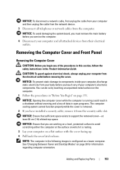
... computer or the surface on which it is removed. 2 If you have installed a security cable, remove it from the security cable slot. Adding and Replacing Parts 153 You can do so by touching an unpainted metal surface on page 151. NOTICE: To avoid damaging the system board, you must remove the...
... computer or the surface on which it is removed. 2 If you have installed a security cable, remove it from the security cable slot. Adding and Replacing Parts 153 You can do so by touching an unpainted metal surface on page 151. NOTICE: To avoid damaging the system board, you must remove the...

User's Guide
Page 154
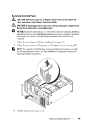
NOTICE: The computer cooling system cannot function properly while the computer cover is not installed. 1 2 3 1 cover latch release 3 cover hinges 2 computer cover 5 Locate the three hinge tabs on the edge of the computer. 6 Grip the sides of the computer cover and pivot the cover up, using the hinges as leverage points. 7 Release the cover from the hinge tabs and set it aside in a secure location. Do not attempt to boot the computer before replacing the computer cover. 154 Adding and Replacing Parts
NOTICE: The computer cooling system cannot function properly while the computer cover is not installed. 1 2 3 1 cover latch release 3 cover hinges 2 computer cover 5 Locate the three hinge tabs on the edge of the computer. 6 Grip the sides of the computer cover and pivot the cover up, using the hinges as leverage points. 7 Release the cover from the hinge tabs and set it aside in a secure location. Do not attempt to boot the computer before replacing the computer cover. 154 Adding and Replacing Parts
User's Guide
Page 155
... of your body before removing the cover. CAUTION: To guard against electrical shock, always unplug your computer from your computer's electronic components. Adding and Replacing Parts 155
... of your body before removing the cover. CAUTION: To guard against electrical shock, always unplug your computer from your computer's electronic components. Adding and Replacing Parts 155
User's Guide
Page 156
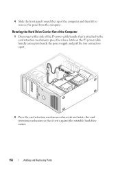
Rotating the Hard Drive Carrier Out of the Computer 1 Disconnect either side of the computer and then lift to the card retention mechanism: press the release latch on the P3 power-cable bundle connectors beside the power supply and pull the two connectors apart. 2 Press the card retention mechanism release-tab and rotate the card retention mechanism so that it rests against the rotatable hard-drive carrier. 156 Adding and Replacing Parts 4 Slide the front panel toward the top of the P3 power-cable bundle that is attached to remove the panel from the computer.
Rotating the Hard Drive Carrier Out of the Computer 1 Disconnect either side of the computer and then lift to the card retention mechanism: press the release latch on the P3 power-cable bundle connectors beside the power supply and pull the two connectors apart. 2 Press the card retention mechanism release-tab and rotate the card retention mechanism so that it rests against the rotatable hard-drive carrier. 156 Adding and Replacing Parts 4 Slide the front panel toward the top of the P3 power-cable bundle that is attached to remove the panel from the computer.
User's Guide
Page 157
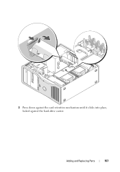
Adding and Replacing Parts 157 3 Press down against the card retention mechanism until it clicks into place, locked against the hard-drive carrier.
Adding and Replacing Parts 157 3 Press down against the card retention mechanism until it clicks into place, locked against the hard-drive carrier.
User's Guide
Page 158
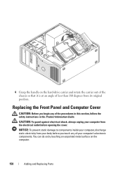
4 Grasp the handle on the computer. 158 Adding and Replacing Parts CAUTION: To guard against electrical shock, always unplug your computer from its original position. Replacing the Front Panel and Computer Cover CAUTION: Before you touch ...
4 Grasp the handle on the computer. 158 Adding and Replacing Parts CAUTION: To guard against electrical shock, always unplug your computer from its original position. Replacing the Front Panel and Computer Cover CAUTION: Before you touch ...
User's Guide
Page 159
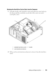
Adding and Replacing Parts 159 Rotating the Hard-Drive Carrier Back into the Computer 1 Grasp the handle on the hard-drive carrier and rotate the carrier back into the chassis until the metal tabs on each side of the carrier are seated, securing the carrier. 2 1 3 1 rotatable hard-drive carrier 2 handle 3 card-retention mechanism 2 Pull up on the card retention mechanism to release it from the hard-drive carrier.
Adding and Replacing Parts 159 Rotating the Hard-Drive Carrier Back into the Computer 1 Grasp the handle on the hard-drive carrier and rotate the carrier back into the chassis until the metal tabs on each side of the carrier are seated, securing the carrier. 2 1 3 1 rotatable hard-drive carrier 2 handle 3 card-retention mechanism 2 Pull up on the card retention mechanism to release it from the hard-drive carrier.
User's Guide
Page 160
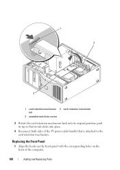
Replacing the Front Panel 1 Align the hooks on the front panel with the corresponding holes on the front of the P3 power-cable bundle that its original position; push its tip so that is attached to the card retention mechanism. 1 2 3 1 card-retention mechanism 2 card-retention mechanism tab 3 rotatable hard-drive carrier 3 Rotate the card retention mechanism back into its tab clicks into place. 4 Reconnect both sides of the computer. 160 Adding and Replacing Parts
Replacing the Front Panel 1 Align the hooks on the front panel with the corresponding holes on the front of the P3 power-cable bundle that its original position; push its tip so that is attached to the card retention mechanism. 1 2 3 1 card-retention mechanism 2 card-retention mechanism tab 3 rotatable hard-drive carrier 3 Rotate the card retention mechanism back into its tab clicks into place. 4 Reconnect both sides of the computer. 160 Adding and Replacing Parts
User's Guide
Page 161
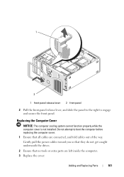
... so that they do not get caught underneath the drives. 2 Ensure that all cables are left inside the computer. 3 Replace the cover: Adding and Replacing Parts 161 1 2 1 front-panel release lever 2 front panel 2 Pull the front-panel release lever, and slide the panel to the right to boot the computer... before replacing the computer cover. 1 Ensure that no tools or extra parts are connected, and fold cables out of the way. Do not attempt to engage and secure the front panel. Replacing the Computer Cover NOTICE: ...
... so that they do not get caught underneath the drives. 2 Ensure that all cables are left inside the computer. 3 Replace the cover: Adding and Replacing Parts 161 1 2 1 front-panel release lever 2 front panel 2 Pull the front-panel release lever, and slide the panel to the right to boot the computer... before replacing the computer cover. 1 Ensure that no tools or extra parts are connected, and fold cables out of the way. Do not attempt to engage and secure the front panel. Replacing the Computer Cover NOTICE: ...


