
Owner's Manual
Page 35
Installing the System Board 1. Connect the cables to the chassis. 3. Align the system board to the port connectors on the rear of the chassis and place the system board in After Working Inside Your Computer. Install: a) processor b) memory module(s) c) heat-sink fan d) ...
Installing the System Board 1. Connect the cables to the chassis. 3. Align the system board to the port connectors on the rear of the chassis and place the system board in After Working Inside Your Computer. Install: a) processor b) memory module(s) c) heat-sink fan d) ...

Owner's Manual
Page 36
.... system fan 1 connector 18. system fan 2 connector 21. RTCRST jumper 28. 24-pin power connector 29. internal USB 2.0 connector 30. PCIe x16 slot (accelerated graphics port) 6. hard drive temperature sensor 14. PSWD jumper 23. PCIe x1 slot 5. HDD temperature sensor connector 20. internal USB 2.0 connector 26. coin-cell battery 17. internal...
.... system fan 1 connector 18. system fan 2 connector 21. RTCRST jumper 28. 24-pin power connector 29. internal USB 2.0 connector 30. PCIe x16 slot (accelerated graphics port) 6. hard drive temperature sensor 14. PSWD jumper 23. PCIe x1 slot 5. HDD temperature sensor connector 20. internal USB 2.0 connector 26. coin-cell battery 17. internal...
Owner's Manual
Page 41
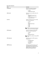
... configure the internal SATA hard-drive controller. The options are: • Enable Boot Support • Front USB Ports • Rear USB Ports • USB3 Ports This field controls if the hard drive errors for the integrated drives are : • Disabled • Enabled (Default ... of the SMART (Self Monitoring Analysis and Reporting Technology) specification. 41 System Configuration Option Integrated NIC USB Controller Serial Port SATA Operation USB Configuration SMART Reporting Description Allows you to configure the integrated network controller. The options are reported during system...
... configure the internal SATA hard-drive controller. The options are: • Enable Boot Support • Front USB Ports • Rear USB Ports • USB3 Ports This field controls if the hard drive errors for the integrated drives are : • Disabled • Enabled (Default ... of the SMART (Self Monitoring Analysis and Reporting Technology) specification. 41 System Configuration Option Integrated NIC USB Controller Serial Port SATA Operation USB Configuration SMART Reporting Description Allows you to configure the integrated network controller. The options are reported during system...
Owner's Manual
Page 60
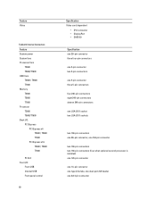
Internal Connectors Feature System power System fans Processor fans T3600 T5600/T7600 HDD fans T3600 / T5600 T7600 Memory T3600 T5600 T7600 Processor T3600 T5600/T7600 Back I/O: PCI Express PCI Express x4 T3600 / T5600 T7600 PCI Express x16 T3600 / T5600 T7600 PCI 2.3 Front I/O: Front USB Internal USB Front panel control 60 Specification Video card dependent • DVI ...connectors two 164-pin connectors (four when optional second processor is installed) one 124-pin connector one 14-pin connector one type A female, one dual-port 2x5 header one 2x14 pin connector Feature Video Table 23.
Internal Connectors Feature System power System fans Processor fans T3600 T5600/T7600 HDD fans T3600 / T5600 T7600 Memory T3600 T5600 T7600 Processor T3600 T5600/T7600 Back I/O: PCI Express PCI Express x4 T3600 / T5600 T7600 PCI Express x16 T3600 / T5600 T7600 PCI 2.3 Front I/O: Front USB Internal USB Front panel control 60 Specification Video card dependent • DVI ...connectors two 164-pin connectors (four when optional second processor is installed) one 124-pin connector one 14-pin connector one type A female, one dual-port 2x5 header one 2x14 pin connector Feature Video Table 23.


