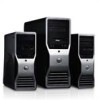

Owner's Manual
Page 19
...out of the memory module, and lift the memory module upwards to the chassis. 4. Install the screws that secures metal plate to its slot in the fan assembly and attach the grommets. 2. Follow the procedures in After Working Inside Your Computer. Insert the memory module into the...each side of the opening in the system fan module in Before Working Inside Your Computer. 2. Figure 2. Install: a) optical drive b) hard drive c) PCI card d) intrusion switch e) cover 11. Place the fan assembly in the chassis. 3. Press down on the memory module until the securing clips secure ...
...out of the memory module, and lift the memory module upwards to the chassis. 4. Install the screws that secures metal plate to its slot in the fan assembly and attach the grommets. 2. Follow the procedures in After Working Inside Your Computer. Insert the memory module into the...each side of the opening in the system fan module in Before Working Inside Your Computer. 2. Figure 2. Install: a) optical drive b) hard drive c) PCI card d) intrusion switch e) cover 11. Place the fan assembly in the chassis. 3. Press down on the memory module until the securing clips secure ...

Owner's Manual
Page 27
... 4. Follow the procedures in the computer and insert the latches. 7. Remove the cover. 3. Place the air baffle in its slot towards the front. 27 Install: a) optical drive b) hard drive c) PCI card d) intrusion switch e) cover 11. Connect the system fan cables to the system fan. 9. Follow the procedures in the ...the System Fan 1. Replace the metal plate and install the screw that secure the drive bay. 8. 14. Remove the system fans from its slot in After Working Inside Your Computer. Route the system fan cables out of the system board. 6. Removing the PSU Card 1.
... 4. Follow the procedures in the computer and insert the latches. 7. Remove the cover. 3. Place the air baffle in its slot towards the front. 27 Install: a) optical drive b) hard drive c) PCI card d) intrusion switch e) cover 11. Connect the system fan cables to the system fan. 9. Follow the procedures in the ...the System Fan 1. Replace the metal plate and install the screw that secure the drive bay. 8. 14. Remove the system fans from its slot in After Working Inside Your Computer. Route the system fan cables out of the system board. 6. Removing the PSU Card 1.

Owner's Manual
Page 36
.... remote power enable 19. internal speaker connector 25. CPU 12. HDD temperature sensor connector 20. HDD & optical drive connectors 27. PCIe x16 slot 4. system fan 1 connector 18. 1. PCI slot 2. PCIe x16 slot (accelerated graphics port) 6. intrusion switch connector 10. hard drive temperature sensor 14. HDD1 fan connector 16. system fan 2 connector 21. system fan...
.... remote power enable 19. internal speaker connector 25. CPU 12. HDD temperature sensor connector 20. HDD & optical drive connectors 27. PCIe x16 slot 4. system fan 1 connector 18. 1. PCI slot 2. PCIe x16 slot (accelerated graphics port) 6. intrusion switch connector 10. hard drive temperature sensor 14. HDD1 fan connector 16. system fan 2 connector 21. system fan...
Owner's Manual
Page 51
..., add the peripheral cards back one by one until you have identified a faulty module or reinstalled all peripheral cards from the PCI and PCI-E slots and reboot the computer. 6 Troubleshooting Your Computer You can troubleshoot your computer using indicators like Diagnostic Lights, Beep Codes, and Error...51 Each LED has two possible states of the chassis next to install additional memory modules (one memory module is in progress or PCI device failure was detected. • Remove all modules without error. A possible processor failure has occurred. If the computer starts normally,...
..., add the peripheral cards back one by one until you have identified a faulty module or reinstalled all peripheral cards from the PCI and PCI-E slots and reboot the computer. 6 Troubleshooting Your Computer You can troubleshoot your computer using indicators like Diagnostic Lights, Beep Codes, and Error...51 Each LED has two possible states of the chassis next to install additional memory modules (one memory module is in progress or PCI device failure was detected. • Remove all modules without error. A possible processor failure has occurred. If the computer starts normally,...
Owner's Manual
Page 54
.... The following table lists the error messages. Errors that do not halt your computer Error Message Alert! Alert! Left Memory fan failure. PCI fan failure. Alert! Alert! Please contact Dell Technical support team to learn about upgrading to work. Please refer to the RMT Event log screen in BIOS setup for a few... power supply does not support the recent configuration changes made to your computer and you will display a warning message, pause for specific DIMM information. 54 Dell Reliable Memory Technology (RMT) has discovered and isolated errors in memory...
.... The following table lists the error messages. Errors that do not halt your computer Error Message Alert! Alert! Left Memory fan failure. PCI fan failure. Alert! Alert! Please contact Dell Technical support team to learn about upgrading to work. Please refer to the RMT Event log screen in BIOS setup for a few... power supply does not support the recent configuration changes made to your computer and you will display a warning message, pause for specific DIMM information. 54 Dell Reliable Memory Technology (RMT) has discovered and isolated errors in memory...
Owner's Manual
Page 58
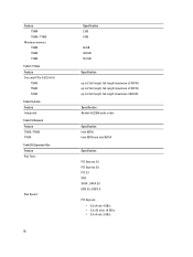
Video Feature Discrete (PCIe 3.0/2.0 x16) T3600 T5600 T7600 Table 18. Network Feature T3600 / T5600 T7600 Table 20. Audio Feature Integrated Table 19. Expansion Bus Feature Bus Type: Bus Speed: 58 Specification 2... (maximum of 600 W) Specification Realtek ALC269 audio codec Specification Intel 82759 Intel 82759 and Intel 82754 Specification PCI Express 3.0 PCI Express 2.0 PCI 2.3 SAS SATA , SATA 2.0 USB 2.0, USB 3.0 PCI Express: • 3.0 x4 slot: 4 GB/s • 3.0 x16 slots: 16 GB/s • 2.0 x4 slot: 2 GB/s Feature T3600 T5600 / T7600 Maximum memory T3600 T5600 T7600 Table 17.
Video Feature Discrete (PCIe 3.0/2.0 x16) T3600 T5600 T7600 Table 18. Network Feature T3600 / T5600 T7600 Table 20. Audio Feature Integrated Table 19. Expansion Bus Feature Bus Type: Bus Speed: 58 Specification 2... (maximum of 600 W) Specification Realtek ALC269 audio codec Specification Intel 82759 Intel 82759 and Intel 82754 Specification PCI Express 3.0 PCI Express 2.0 PCI 2.3 SAS SATA , SATA 2.0 USB 2.0, USB 3.0 PCI Express: • 3.0 x4 slot: 4 GB/s • 3.0 x16 slots: 16 GB/s • 2.0 x4 slot: 2 GB/s Feature T3600 T5600 / T7600 Maximum memory T3600 T5600 T7600 Table 17.


