Page 3
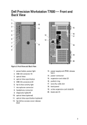
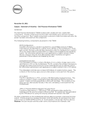
... 14. hard-drive activity light 7. optical drive eject button (optional) 12. hard drive access cover-release latch 13. back panel 19. blank slot (1) 3 security cable slot 18. optical drive eject button 5. active expansion card slots (5) 20. optical drive 4. Front and Back View Figure 3. USB 3.0 connector (1) 3. Front View and Back View 1. headphone connector 9. expansion card slots (2) 16. Dell Precision Workstation...
... 14. hard-drive activity light 7. optical drive eject button (optional) 12. hard drive access cover-release latch 13. back panel 19. blank slot (1) 3 security cable slot 18. optical drive eject button 5. active expansion card slots (5) 20. optical drive 4. Front and Back View Figure 3. USB 3.0 connector (1) 3. Front View and Back View 1. headphone connector 9. expansion card slots (2) 16. Dell Precision Workstation...
Owner's Manual
Page 3
...)...7 Installing the Power Supply Unit (PSU)...8 Removing the Cover...8 Installing the Cover...9 Removing the Optical Drive ...9 Installing the Optical Drive ...12 Removing the Thermal Sensor...12 Installing the Thermal Sensor...12 Removing the Hard Drive...12 Installing the Hard Drive ...14 Removing the System Fan...14 Installing the System Fan...19 Removing the Memory...19 Installing...
...)...7 Installing the Power Supply Unit (PSU)...8 Removing the Cover...8 Installing the Cover...9 Removing the Optical Drive ...9 Installing the Optical Drive ...12 Removing the Thermal Sensor...12 Installing the Thermal Sensor...12 Removing the Hard Drive...12 Installing the Hard Drive ...14 Removing the System Fan...14 Installing the System Fan...19 Removing the Memory...19 Installing...
Owner's Manual
Page 12
... the Thermal Sensor NOTE: The Thermal Sensor is an optional component and your computer may not ship with it from the hard drive. 12 Follow the procedures in Before Working Inside Your Computer. 2. Follow the procedures in After Working Inside Your Computer. Follow the ... and your computer may not ship with it to release the latch and thread the cables into the holder. 3. Removing the Hard Drive 1. Connect the data cable to the back of the optical drive. 5. Press on the clasp to the computer. 2. Remove the cover. 3. Install the cover. 6. Remove the cover....
... the Thermal Sensor NOTE: The Thermal Sensor is an optional component and your computer may not ship with it from the hard drive. 12 Follow the procedures in Before Working Inside Your Computer. 2. Follow the procedures in After Working Inside Your Computer. Follow the ... and your computer may not ship with it to release the latch and thread the cables into the holder. 3. Removing the Hard Drive 1. Connect the data cable to the back of the optical drive. 5. Press on the clasp to the computer. 2. Remove the cover. 3. Install the cover. 6. Remove the cover....

Owner's Manual
Page 13
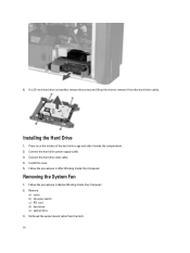
Press in on the latches on either side of the compartment. 13 4. Slide the hard drive out of the hard drive bracket. 5.
Press in on the latches on either side of the compartment. 13 4. Slide the hard drive out of the hard drive bracket. 5.
Owner's Manual
Page 14
... it from the latch. 14 Connect the hard drive data cable. 4. Unthread the system board cable from the hard-drive caddy. 6. Remove: a) cover b) intrusion switch c) PCI card d) hard drive e) optical drive 3. Follow the procedures in Before Working Inside Your Computer. 2. Install the cover. 5. Connect the hard drive power supply cable. 3. Installing the Hard Drive 1. Follow the procedures in After Working Inside...
... it from the latch. 14 Connect the hard drive data cable. 4. Unthread the system board cable from the hard-drive caddy. 6. Remove: a) cover b) intrusion switch c) PCI card d) hard drive e) optical drive 3. Follow the procedures in Before Working Inside Your Computer. 2. Install the cover. 5. Connect the hard drive power supply cable. 3. Installing the Hard Drive 1. Follow the procedures in After Working Inside...

Owner's Manual
Page 19
...Press down on the memory module until the securing clips secure the memory in the computer and insert the latches. 7. Install: a) optical drive b) hard drive c) PCI card d) intrusion switch e) cover 11. Removing the Memory 1. Follow the procedures in After Working Inside Your Computer. Press down on...Computer. 2. Figure 2. Connect the system fan cables to the chassis. 4. Replace the metal plate and install the screw that secure the drive bay. 8. Route and connect the system board cable to the system fan. 9. Follow the procedures in the fan assembly and attach the ...
...Press down on the memory module until the securing clips secure the memory in the computer and insert the latches. 7. Install: a) optical drive b) hard drive c) PCI card d) intrusion switch e) cover 11. Removing the Memory 1. Follow the procedures in After Working Inside Your Computer. Press down on...Computer. 2. Figure 2. Connect the system fan cables to the chassis. 4. Replace the metal plate and install the screw that secure the drive bay. 8. Route and connect the system board cable to the system fan. 9. Follow the procedures in the fan assembly and attach the ...

Owner's Manual
Page 23
c) PCI card d) hard drive e) optical drive 3. Remove the screw that secures metal plate to release it. 23 Press the latches on either side of the metal plate to the system fan. 5. Unthread the system board cable from the latch. 4.
c) PCI card d) hard drive e) optical drive 3. Remove the screw that secures metal plate to release it. 23 Press the latches on either side of the metal plate to the system fan. 5. Unthread the system board cable from the latch. 4.

Owner's Manual
Page 27
... Fan 1. Connect the system fan cables to the chassis. 4. Install: a) optical drive b) hard drive c) PCI card d) intrusion switch e) cover 11. Place the air baffle in its slot towards the front. 27 Replace the metal plate and install the screw that secure the drive bay. 8. Slide the baffle cover from the system fan assembly. Install...
... Fan 1. Connect the system fan cables to the chassis. 4. Install: a) optical drive b) hard drive c) PCI card d) intrusion switch e) cover 11. Place the air baffle in its slot towards the front. 27 Replace the metal plate and install the screw that secure the drive bay. 8. Slide the baffle cover from the system fan assembly. Install...

Owner's Manual
Page 33
Removing the System Board 1. Follow the procedures in After Working Inside Your Computer. Remove: a) PSU b) cover c) optical drive d) coin-cell battery e) thermal sensor f) hard drive g) system fan h) PSU card i) PCI card 33 Follow the procedures in Before Working On Your Computer. 2. Replace the speaker and fix the clasp. 2. Connect the speaker cable to the system board. 3. Install the cover. 4. Installing the Speaker 1. 4. Press down the clasp, lift and remove the speaker.
Removing the System Board 1. Follow the procedures in After Working Inside Your Computer. Remove: a) PSU b) cover c) optical drive d) coin-cell battery e) thermal sensor f) hard drive g) system fan h) PSU card i) PCI card 33 Follow the procedures in Before Working On Your Computer. 2. Replace the speaker and fix the clasp. 2. Connect the speaker cable to the system board. 3. Install the cover. 4. Installing the Speaker 1. 4. Press down the clasp, lift and remove the speaker.

Owner's Manual
Page 35
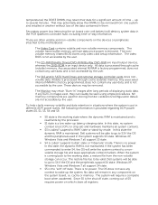
... the chassis. 2. Install: a) processor b) memory module(s) c) heat-sink fan d) heat sink e) speakers f) front input/output (I/O) panel g) PCI card h) PSU card i) system fan j) hard drive k) thermal sensor l) coin-cell battery m) optical drive n) cover o) PSU 5. Connect the cables to the chassis. 3. Installing the System Board 1. System Board Components The following image displays the system board...
... the chassis. 2. Install: a) processor b) memory module(s) c) heat-sink fan d) heat sink e) speakers f) front input/output (I/O) panel g) PCI card h) PSU card i) system fan j) hard drive k) thermal sensor l) coin-cell battery m) optical drive n) cover o) PSU 5. Connect the cables to the chassis. 3. Installing the System Board 1. System Board Components The following image displays the system board...

Owner's Manual
Page 36
... enable 19. PSWD jumper 23. PCIe x16 slot (wired as x4) 7. HDD temperature sensor connector 20. HDD & optical drive connectors 27. PCIe x16 slot (wired as x4) 3. USB 3.0 front panel connector 8. DIMM slots 9. hard drive temperature sensor 14. front panel audio connector 15. PCI slot 2. PCIe x16 slot 4. PCIe x16 slot (accelerated graphics...
... enable 19. PSWD jumper 23. PCIe x16 slot (wired as x4) 7. HDD temperature sensor connector 20. HDD & optical drive connectors 27. PCIe x16 slot (wired as x4) 3. USB 3.0 front panel connector 8. DIMM slots 9. hard drive temperature sensor 14. front panel audio connector 15. PCI slot 2. PCIe x16 slot 4. PCIe x16 slot (accelerated graphics...
Owner's Manual
Page 39
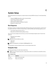
... the diagnostic option. Table 1. Navigation Keys Keys Navigation Up arrow Moves to the next field. 39 During the Power-on Self Test (POST), when the Dell logo appears, you can : • Change the NVRAM settings after you add or remove hardware • View the system hardware configuration • Enable or disable... Boot Sequence Boot Sequence allows you to bypass the System Setup‐defined boot device order and boot directly to a specific device (for example: optical drive or hard drive). The boot sequence screen also displays the option to access the System Setup screen.
... the diagnostic option. Table 1. Navigation Keys Keys Navigation Up arrow Moves to the next field. 39 During the Power-on Self Test (POST), when the Dell logo appears, you can : • Change the NVRAM settings after you add or remove hardware • View the system hardware configuration • Enable or disable... Boot Sequence Boot Sequence allows you to bypass the System Setup‐defined boot device order and boot directly to a specific device (for example: optical drive or hard drive). The boot sequence screen also displays the option to access the System Setup screen.
Owner's Manual
Page 41
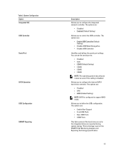
...options are: • Enable Boot Support • Front USB Ports • Rear USB Ports • USB3 Ports This field controls if the hard drive errors for the integrated drives are : • Enable USB Controller (Default Setting) • Disable USB Mass Storage Dev • Disable USB Controller Identifies and defines the ... Analysis and Reporting Technology) specification. 41 The options are : • Disabled • Enabled (Default Setting) Allows you to configure the internal SATA hard-drive controller. Table 3. This technology is configured to control the USB controller.
...options are: • Enable Boot Support • Front USB Ports • Rear USB Ports • USB3 Ports This field controls if the hard drive errors for the integrated drives are : • Enable USB Controller (Default Setting) • Disable USB Mass Storage Dev • Disable USB Controller Identifies and defines the ... Analysis and Reporting Technology) specification. 41 The options are : • Disabled • Enabled (Default Setting) Allows you to configure the internal SATA hard-drive controller. Table 3. This technology is configured to control the USB controller.
Owner's Manual
Page 52
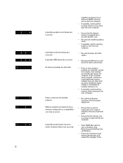
... the modules, then reinstall one at a time) until you have identified a faulty module or reinstalled all internal and external peripherals, and restart the computer. A possible hard drive failure has occurred. installed, try moving it to install additional memory modules (one module and restart the computer. See Removing and Installing Coincell Battery). •...
... the modules, then reinstall one at a time) until you have identified a faulty module or reinstalled all internal and external peripherals, and restart the computer. A possible hard drive failure has occurred. installed, try moving it to install additional memory modules (one module and restart the computer. See Removing and Installing Coincell Battery). •...
Owner's Manual
Page 53
... the hand-off to ensure the boot sequence is correct for the devices installed on the screen identifying a problem with a device (such as the floppy drive or hard drive), check the device to make sure it is functioning properly. • If the operating system is faulty. • Disconnect all... hard drives and optical-drive cables are normally in recovery mode. • Indicates end of POST process. If the computer boots, add the peripheral cards back one by one until ...
... the hand-off to ensure the boot sequence is correct for the devices installed on the screen identifying a problem with a device (such as the floppy drive or hard drive), check the device to make sure it is functioning properly. • If the operating system is faulty. • Disconnect all... hard drives and optical-drive cables are normally in recovery mode. • Indicates end of POST process. If the computer boots, add the peripheral cards back one by one until ...
Owner's Manual
Page 54
... fan failure. Table 12. Errors that do not halt your computer Error Message Alert! Left Memory fan failure. Chipset heat sink not detected. Hard Drive fan1 failure. Please contact Dell Technical support team to learn about upgrading to your computer, but will cause a soft halt of the issue. CPU 0 fan failure. For increased...
... fan failure. Table 12. Errors that do not halt your computer Error Message Alert! Left Memory fan failure. Chipset heat sink not detected. Hard Drive fan1 failure. Please contact Dell Technical support team to learn about upgrading to your computer, but will cause a soft halt of the issue. CPU 0 fan failure. For increased...
Owner's Manual
Page 59
...45 two RJ-45 one ; Feature Table 21. supports one 5.25-inches device, one media card reader, or up to four 2.5-inches hard drives (with optional adapters) two; five USB 2.0, and one USB 3.0 • back panel - supports one 5.25-inches SATA device, ...front panel - Mic-in, headphone-out • back panel - Drives Feature T3600 /T5600 Externally accessible: Slimline SATA optical bays 5.25-inch drive bays Internally accessible 3.5-inch hard drive bays T7600 Externally accessible: Slimline SATA optical bays: 5.25-inch drive bays 3.5-inch hard drive bays Internally accessible Table 22.
...45 two RJ-45 one ; Feature Table 21. supports one 5.25-inches device, one media card reader, or up to four 2.5-inches hard drives (with optional adapters) two; five USB 2.0, and one USB 3.0 • back panel - supports one 5.25-inches SATA device, ...front panel - Mic-in, headphone-out • back panel - Drives Feature T3600 /T5600 Externally accessible: Slimline SATA optical bays 5.25-inch drive bays Internally accessible 3.5-inch hard drive bays T7600 Externally accessible: Slimline SATA optical bays: 5.25-inch drive bays 3.5-inch hard drive bays Internally accessible Table 22.
Owner's Manual
Page 61
...blinking amber light - orange light - see the service manual for specific diagnostic codes. Controls and Lights Feature Power button light: Drive activity light Network link integrity lights (back panel) Network activity lights (back panel) Diagnostic lights: Table 25. system is off...pin connector Specification off - Specification 3 V CR2032 lithium coin cell 100 VAC to the hard drive. yellow light - Feature Front panel audio HDA header HDD Back Panel : SATA T3600 T5600 T7600 Power T3600 T5600 T7600 Table 24. solid white light - blinking white light - solid amber light ...
...blinking amber light - orange light - see the service manual for specific diagnostic codes. Controls and Lights Feature Power button light: Drive activity light Network link integrity lights (back panel) Network activity lights (back panel) Diagnostic lights: Table 25. system is off...pin connector Specification off - Specification 3 V CR2032 lithium coin cell 100 VAC to the hard drive. yellow light - Feature Front panel audio HDA header HDD Back Panel : SATA T3600 T5600 T7600 Power T3600 T5600 T7600 Table 24. solid white light - blinking white light - solid amber light ...
Statement of Volatility
Page 1
... in this memory space are present in the T3600: BIOS Configuration The BIOS information is stored in these devices, however, they do store administrator and/or hard drive encryption passwords if those features are enabled by Dell. The EC contains the software necessary to user...power cord) will lose data once power is removed from a poweroff or low-power state to boot the system. Dell Precision Workstation T3600 Gentlemen: The Dell Precision Workstation T3600 contains both volatile and non-volatile (NV) components. PCH CMOS The PCH, identified as thermal control. Encrypted user ...
... in this memory space are present in the T3600: BIOS Configuration The BIOS information is stored in these devices, however, they do store administrator and/or hard drive encryption passwords if those features are enabled by Dell. The EC contains the software necessary to user...power cord) will lose data once power is removed from a poweroff or low-power state to boot the system. Dell Precision Workstation T3600 Gentlemen: The Dell Precision Workstation T3600 contains both volatile and non-volatile (NV) components. PCH CMOS The PCH, identified as thermal control. Encrypted user ...
Statement of Volatility
Page 2
... does not save any user data, and is the "soft" off state, coming back to be valid. cache or memory. The SAS and/or SATA Hard Drives and optional storage controller cards store nonvolatile data. Any associated internal NVRAM is factory programmed, does not contain any context to S4 if the OS... and the peripherals support S4 state. The Monitor may be removed. In this state, the dynamic RAM is not accessible by the user. Dell systems will destroy system data in them. The system will be able to go to wake up to be removed from the non-volatile storage...
... does not save any user data, and is the "soft" off state, coming back to be valid. cache or memory. The SAS and/or SATA Hard Drives and optional storage controller cards store nonvolatile data. Any associated internal NVRAM is factory programmed, does not contain any context to S4 if the OS... and the peripherals support S4 state. The Monitor may be removed. In this state, the dynamic RAM is not accessible by the user. Dell systems will destroy system data in them. The system will be able to go to wake up to be removed from the non-volatile storage...


