Setup and Features Information Tech Sheet
Page 1
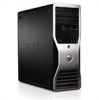
Dell™ Precision™ Workstation T3500 Setup and Features Information Front View 1 10 2 9 3 8 4 5 7 6 1 optical drives (2) 2 optical drive eject button 3 FlexBay (optional floppy drive 4 drive activity light or media card reader) June 2009 Model DCTA About Warnings WARNING: A WARNING indicates a potential for property damage, personal injury, or death.
Dell™ Precision™ Workstation T3500 Setup and Features Information Front View 1 10 2 9 3 8 4 5 7 6 1 optical drives (2) 2 optical drive eject button 3 FlexBay (optional floppy drive 4 drive activity light or media card reader) June 2009 Model DCTA About Warnings WARNING: A WARNING indicates a potential for property damage, personal injury, or death.
Setup and Features Information Tech Sheet
Page 3
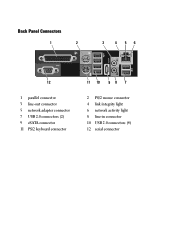
Back Panel Connectors 1 2 3 4 56 12 1 parallel connector 3 line-out connector 5 network adapter connector 7 USB 2.0 connectors (2) 9 eSATA connector 11 PS/2 keyboard connector 11 10 9 8 7 2 PS/2 mouse connector 4 link integrity light 6 network activity light 8 line-in connector 10 USB 2.0 connectors (4) 12 serial connector
Back Panel Connectors 1 2 3 4 56 12 1 parallel connector 3 line-out connector 5 network adapter connector 7 USB 2.0 connectors (2) 9 eSATA connector 11 PS/2 keyboard connector 11 10 9 8 7 2 PS/2 mouse connector 4 link integrity light 6 network activity light 8 line-in connector 10 USB 2.0 connectors (4) 12 serial connector
Setup and Features Information Tech Sheet
Page 4
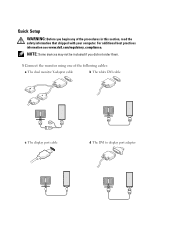
Quick Setup WARNING: Before you did not order them. 1 Connect the monitor using one of the procedures in this section, read the safety information that shipped with your computer. For additional best practices information see www.dell.com/regulatory_compliance. NOTE: Some devices may not be included if you begin any of the following cables: a The dual monitor Y-adapter cable b The white DVI cable c The display port cable d The DVI to display port adapter
Quick Setup WARNING: Before you did not order them. 1 Connect the monitor using one of the procedures in this section, read the safety information that shipped with your computer. For additional best practices information see www.dell.com/regulatory_compliance. NOTE: Some devices may not be included if you begin any of the following cables: a The dual monitor Y-adapter cable b The white DVI cable c The display port cable d The DVI to display port adapter
Setup and Features Information Tech Sheet
Page 5
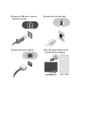
2 Connect a USB device, such as a keyboard or mouse. 3 Connect the network cable. 4 Connect the power cable(s). 5 Press the power buttons on the monitor and the computer.
2 Connect a USB device, such as a keyboard or mouse. 3 Connect the network cable. 4 Connect the power cable(s). 5 Press the power buttons on the monitor and the computer.
Setup and Features Information Tech Sheet
Page 6
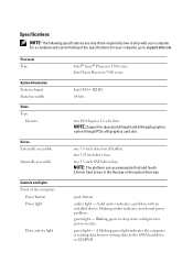
... computer: Power button Power light Drive activity light Intel® Xeon® Processor 3500 series Intel Xeon Processor 5500 series Intel X58+ ICH10 64 bits two PCI Express 2.0 x16 slots NOTE: Support for discrete full height and 3/4 length graphics option through PCIe x16 graphics card slot. solid green for your computer. Processor Type System Information System chipset Data bus width Video Type: Discrete Drives Externally accessible Internally accessible Controls and Lights Front of the specifications for power-on state. A blinking green light indicates...
... computer: Power button Power light Drive activity light Intel® Xeon® Processor 3500 series Intel Xeon Processor 5500 series Intel X58+ ICH10 64 bits two PCI Express 2.0 x16 slots NOTE: Support for discrete full height and 3/4 length graphics option through PCIe x16 graphics card slot. solid green for your computer. Processor Type System Information System chipset Data bus width Video Type: Discrete Drives Externally accessible Internally accessible Controls and Lights Front of the specifications for power-on state. A blinking green light indicates...
Setup and Features Information Tech Sheet
Page 7
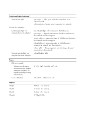
... on integrated network adapter) green light - orange light - A good connection at 100Mbs exists between the network and the computer. yellow light - Controls and Lights (continued) Network link light Rear of the computer: Link integrity light (on integrated network adapter) Network activity light (on the link speed: green light - Solid green indicates connection to the network. System is not connected to a network link integrity light color is not detecting a physical connection to an active network off (no light) -
... on integrated network adapter) green light - orange light - A good connection at 100Mbs exists between the network and the computer. yellow light - Controls and Lights (continued) Network link light Rear of the computer: Link integrity light (on integrated network adapter) Network activity light (on the link speed: green light - Solid green indicates connection to the network. System is not connected to a network link integrity light color is not detecting a physical connection to an active network off (no light) -
Setup and Features Information Tech Sheet
Page 8
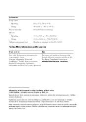
...you need to change without the written permission of Intel Corporation in this text: Dell, the DELL logo, and Dell Precision are registered trademarks of Dell ...Dell Inc. is subject to : See: Find safety best practices information for The safety and regulatory documents that your computer, review shipped with your computer and also see the Warranty information, Terms and Regulatory Compliance Homepage at Conditions(U.S only), Safety instructions, www.dell.com/regulatory_compliance. Trademarks used in the U.S. Regulatory information, Ergonomics information, and End User...
...you need to change without the written permission of Intel Corporation in this text: Dell, the DELL logo, and Dell Precision are registered trademarks of Dell ...Dell Inc. is subject to : See: Find safety best practices information for The safety and regulatory documents that your computer, review shipped with your computer and also see the Warranty information, Terms and Regulatory Compliance Homepage at Conditions(U.S only), Safety instructions, www.dell.com/regulatory_compliance. Trademarks used in the U.S. Regulatory information, Ergonomics information, and End User...
Replacing the Hard-Drive Tray
Page 1
... the Service Manual on the Dell Support website at www.dell.com/regulatory_compliance. Replacing the Hard-Drive Tray on the video card. NOTE: For more information on removing and replacing parts on your computer, see the Regulatory Compliance Homepage at support.dell.com/manuals. 1 Turn off your computer. 2 Disconnect all the external cables from the hard-drive tray, if the hard-drive tray obstructs the cables on Your Dell Precision™ Workstation T3500/T5500 WARNING: Before working inside your...
... the Service Manual on the Dell Support website at www.dell.com/regulatory_compliance. Replacing the Hard-Drive Tray on the video card. NOTE: For more information on removing and replacing parts on your computer, see the Regulatory Compliance Homepage at support.dell.com/manuals. 1 Turn off your computer. 2 Disconnect all the external cables from the hard-drive tray, if the hard-drive tray obstructs the cables on Your Dell Precision™ Workstation T3500/T5500 WARNING: Before working inside your...
Replacing the Hard-Drive Tray
Page 2
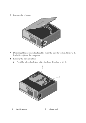
3 Remove the side cover. 4 Disconnect the power and data cables from the hard drive(s) and remove the hard drive(s) from the computer. 5 Remove the hard-drive tray: a Press the release latch and rotate the hard-drive tray to lift it. 1 2 1 hard-drive tray 2 release latch
3 Remove the side cover. 4 Disconnect the power and data cables from the hard drive(s) and remove the hard drive(s) from the computer. 5 Remove the hard-drive tray: a Press the release latch and rotate the hard-drive tray to lift it. 1 2 1 hard-drive tray 2 release latch
Replacing the Hard-Drive Tray
Page 3
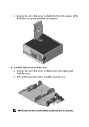
b Remove the screws that secure the filler panel to the replacement hard-drive tray. lift the hard-drive tray up and away from the computer. 6 Install the replacement hard-drive tray: a Remove the screws that secure the hard-drive tray to install a second hard drive at a later time. b Lift the filler panel and slide it out of the hard-drive tray. NOTE: Retain the filler panel to the chassis;
b Remove the screws that secure the filler panel to the replacement hard-drive tray. lift the hard-drive tray up and away from the computer. 6 Install the replacement hard-drive tray: a Remove the screws that secure the hard-drive tray to install a second hard drive at a later time. b Lift the filler panel and slide it out of the hard-drive tray. NOTE: Retain the filler panel to the chassis;
Replacing the Hard-Drive Tray
Page 4
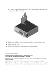
Printed in this text: Dell, the DELL logo, and Dell Precision are trademarks of Dell Inc. Trademarks used in this document to refer to the chassis with the screws from the removed hard-drive tray. 7 Replace the hard drive and connect the hard-drive power and data cables. 8 Replace the side cover. 9 Connect all the external cables and turn on the computer. Dell Inc. Other trademarks and trade names may be used in the U.S.A. All rights...
Printed in this text: Dell, the DELL logo, and Dell Precision are trademarks of Dell Inc. Trademarks used in this document to refer to the chassis with the screws from the removed hard-drive tray. 7 Replace the hard drive and connect the hard-drive power and data cables. 8 Replace the side cover. 9 Connect all the external cables and turn on the computer. Dell Inc. Other trademarks and trade names may be used in the U.S.A. All rights...


