Service Manual
Page 4
... Route the cable through its cabling channel. 2. Replace the I/O board (see Replacing the Keyboard). 10. Replace the keyboard and LED cover (see Replacing the I/O Board). 4. Replace the card in the WLAN/WiMax slot, if it was present (see Replacing the Modem). 21. Replace the modem (see Replacing a WLAN Card). 19. Replace the hard drive (see Replacing the Palm Rest Assembly). 9. Back to...
... Route the cable through its cabling channel. 2. Replace the I/O board (see Replacing the Keyboard). 10. Replace the keyboard and LED cover (see Replacing the I/O Board). 4. Replace the card in the WLAN/WiMax slot, if it was present (see Replacing the Modem). 21. Replace the modem (see Replacing a WLAN Card). 19. Replace the hard drive (see Replacing the Palm Rest Assembly). 9. Back to...
Service Manual
Page 8
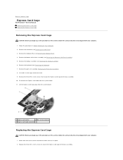
Remove the modular drive (see Removing the Keyboard). 7. Remove the keyboard (see Removing the Modular Drive). 4. If a card is in ... from the system board. 1 Express card carrier 2 M2 x 3-mm screw (3) 3 Express card cable connector Replacing the Express Card Cage CAUTION: Before you begin any of the procedures in this section, follow the safety instructions that... to the base assembly. 10. Back to Contents Page Express Card Cage Dell Precision™ Service Manual Removing the Express Card Cage Replacing the Express Card Cage Removing the Express Card Cage CAUTION: Before you begin...
Remove the modular drive (see Removing the Keyboard). 7. Remove the keyboard (see Removing the Modular Drive). 4. If a card is in ... from the system board. 1 Express card carrier 2 M2 x 3-mm screw (3) 3 Express card cable connector Replacing the Express Card Cage CAUTION: Before you begin any of the procedures in this section, follow the safety instructions that... to the base assembly. 10. Back to Contents Page Express Card Cage Dell Precision™ Service Manual Removing the Express Card Cage Replacing the Express Card Cage Removing the Express Card Cage CAUTION: Before you begin...

Service Manual
Page 9
Replace the bottom of the base assembly (see Replacing the Modular Drive). 9. 3. Back to the system board. 4. Replace the modular drive (see Replacing the Bottom of the Base Assembly). 8. Replace the display assembly (see Replacing the Keyboard). 6. Replace the palm rest assembly (Replacing the Palm Rest Assembly). 5. Replace the keyboard (see Replacing the Display Assembly). 7. Follow the procedure After Working on Your Computer. Reconnect the Express card cable to Contents Page Replace the hard drive (see Replacing the Hard Drive). 10.
Replace the bottom of the base assembly (see Replacing the Modular Drive). 9. 3. Back to the system board. 4. Replace the modular drive (see Replacing the Bottom of the Base Assembly). 8. Replace the display assembly (see Replacing the Keyboard). 6. Replace the palm rest assembly (Replacing the Palm Rest Assembly). 5. Replace the keyboard (see Replacing the Display Assembly). 7. Follow the procedure After Working on Your Computer. Reconnect the Express card cable to Contents Page Replace the hard drive (see Replacing the Hard Drive). 10.

Service Manual
Page 35
..., and time-consuming to seat the keyboard properly. 2. Follow the procedures in this section, follow the safety instructions that shipped with your computer. 1. Carefully press each side to Contents Page Keyboard Dell Precision™ Service Manual Removing the Keyboard Replacing the Keyboard Removing the Keyboard CAUTION: Before you begin any of the keyboard only, then lift out at an...
..., and time-consuming to seat the keyboard properly. 2. Follow the procedures in this section, follow the safety instructions that shipped with your computer. 1. Carefully press each side to Contents Page Keyboard Dell Precision™ Service Manual Removing the Keyboard Replacing the Keyboard Removing the Keyboard CAUTION: Before you begin any of the keyboard only, then lift out at an...

Service Manual
Page 36
Back to Contents Page Follow the procedure After Working on Your Computer. 1 keyboard connector 2 tabs (5) 3 M2 x 3-mm screw (2) 4. Close the display and turn the computer over. 6. Replace the LED cover (see Replacing the LED Cover). 5.
Back to Contents Page Follow the procedure After Working on Your Computer. 1 keyboard connector 2 tabs (5) 3 M2 x 3-mm screw (2) 4. Close the display and turn the computer over. 6. Replace the LED cover (see Replacing the LED Cover). 5.
Service Manual
Page 44
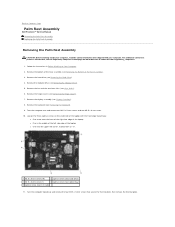
Back to Contents Page Palm Rest Assembly Dell Precision™ Service Manual Removing the Palm Rest Assembly Replacing the Palm Rest Assembly Removing the Palm Rest Assembly CAUTION: Before working inside your computer. Remove the bottom of the base assembly (...M2.5 x 5-mm screws that shipped with the front edge toward you: l One screw near I/O card) 11. Remove the display assembly (see Removing the Keyboard). 9. For additional safety best practices information, see Removing the Hinge Covers). 7. Remove the hinge covers (see the Regulatory Compliance Homepage on Your Computer. 2....
Back to Contents Page Palm Rest Assembly Dell Precision™ Service Manual Removing the Palm Rest Assembly Replacing the Palm Rest Assembly Removing the Palm Rest Assembly CAUTION: Before working inside your computer. Remove the bottom of the base assembly (...M2.5 x 5-mm screws that shipped with the front edge toward you: l One screw near I/O card) 11. Remove the display assembly (see Removing the Keyboard). 9. For additional safety best practices information, see Removing the Hinge Covers). 7. Remove the hinge covers (see the Regulatory Compliance Homepage on Your Computer. 2....

Service Manual
Page 46
... Fan). 13. Angle and connect the right side of the Base Assembly). 18. Replace the discrete graphics heat sink (see Replacing the Keyboard). 15. Turn the computer topside up . 7. Replace the hinge covers (see Replacing the Bottom of the palm rest, then lower and snap the left side edge of the computer to secure the...
... Fan). 13. Angle and connect the right side of the Base Assembly). 18. Replace the discrete graphics heat sink (see Replacing the Keyboard). 15. Turn the computer topside up . 7. Replace the hinge covers (see Replacing the Bottom of the palm rest, then lower and snap the left side edge of the computer to secure the...

Service Manual
Page 47
... remove the wireless card, memory or processor from the system board. 17. Remove the keyboard (see Removing the Discrete Graphics Heat Sink). 13. Remove the discrete graphics heat sink (see Removing the Keyboard). 10. Remove three M2.5 x 5-mm screws labeled with your computer. Remove the hinge...Remove the display assembly (see Removing the Bottom of the base assembly to Contents Page DC Power Cable Dell Precision™ Service Manual Removing the DC Power Cable Replacing the DC Power Cable Removing the DC Power Cable CAUTION: Before working inside your computer, read the safety...
... remove the wireless card, memory or processor from the system board. 17. Remove the keyboard (see Removing the Discrete Graphics Heat Sink). 13. Remove the discrete graphics heat sink (see Removing the Keyboard). 10. Remove three M2.5 x 5-mm screws labeled with your computer. Remove the hinge...Remove the display assembly (see Removing the Bottom of the base assembly to Contents Page DC Power Cable Dell Precision™ Service Manual Removing the DC Power Cable Replacing the DC Power Cable Removing the DC Power Cable CAUTION: Before working inside your computer, read the safety...

Service Manual
Page 48
... (see the Regulatory Compliance Homepage on www.dell.com at: www.dell.com/regulatory_compliance. 1. Replace the hard drive (see Replacing the Display Assembly). 13. Replace the display assembly (see Replacing the Hard Drive). 17. Replace the system board (see Replacing the Modular Drive). 16. Replace the modular drive (see Replacing the System Board Assembly). 4. Replace the discrete graphics heat sink (see...
... (see the Regulatory Compliance Homepage on www.dell.com at: www.dell.com/regulatory_compliance. 1. Replace the hard drive (see Replacing the Display Assembly). 13. Replace the display assembly (see Replacing the Hard Drive). 17. Replace the system board (see Replacing the Modular Drive). 16. Replace the modular drive (see Replacing the System Board Assembly). 4. Replace the discrete graphics heat sink (see...

Service Manual
Page 49
...card reader cable from the base assembly. 1 SD card reader assembly 2 M2 x 3-mm screw (2) 3 SD card reader cable connector Replacing the SD Card Reader CAUTION: Before you begin any of the procedures in this section, follow the safety instructions that shipped with your computer... Replace the two M2.5 x 3-mm screws to Contents Page SD Card Reader Dell Precision™ Service Manual Removing the SD Card Reader Replacing the SD Card Reader Removing the SD Card Reader CAUTION: Before you begin any of the Base Assembly). 5. Remove the display assembly (see Removing the Keyboard...
...card reader cable from the base assembly. 1 SD card reader assembly 2 M2 x 3-mm screw (2) 3 SD card reader cable connector Replacing the SD Card Reader CAUTION: Before you begin any of the procedures in this section, follow the safety instructions that shipped with your computer... Replace the two M2.5 x 3-mm screws to Contents Page SD Card Reader Dell Precision™ Service Manual Removing the SD Card Reader Replacing the SD Card Reader Removing the SD Card Reader CAUTION: Before you begin any of the Base Assembly). 5. Remove the display assembly (see Removing the Keyboard...

Service Manual
Page 50
3. Replace the hard drive (see Replacing the Bottom of the Base Assembly). 10. Replace the palm rest assembly (Replacing the Palm Rest Assembly). 5. Replace the bottom of the base assembly (see Replacing the Hard Drive). 9. Replace the keyboard (see Replacing the Display Assembly). 7. Replace the display assembly (see Replacing the Keyboard). 6. Follow the procedure After Working on Your Computer. Back to the system board. 4. Connect the SD card reader cable to Contents Page Replace the modular drive (see Replacing the Modular Drive). 8.
3. Replace the hard drive (see Replacing the Bottom of the Base Assembly). 10. Replace the palm rest assembly (Replacing the Palm Rest Assembly). 5. Replace the bottom of the base assembly (see Replacing the Hard Drive). 9. Replace the keyboard (see Replacing the Display Assembly). 7. Replace the display assembly (see Replacing the Keyboard). 6. Follow the procedure After Working on Your Computer. Back to the system board. 4. Connect the SD card reader cable to Contents Page Replace the modular drive (see Replacing the Modular Drive). 8.

Service Manual
Page 51
...have a fingerprint reader, ignore steps to Contents Page Right Speaker Grill and Fingerprint Reader Dell Precision™ Service Manual Removing the Right Speaker Grill and Fingerprint Reader Replacing the Right Speaker Grill and Fingerprint Reader Removing the Right Speaker Grill and Fingerprint Reader...the base assembly (see the Regulatory Compliance Homepage on www.dell.com at: www.dell.com/regulatory_compliance. For additional safety best practices information, see Removing the Bottom of the Base Assembly). 7. Remove the keyboard (see Removing the Modular Drive). 4. Remove the plastic...
...have a fingerprint reader, ignore steps to Contents Page Right Speaker Grill and Fingerprint Reader Dell Precision™ Service Manual Removing the Right Speaker Grill and Fingerprint Reader Replacing the Right Speaker Grill and Fingerprint Reader Removing the Right Speaker Grill and Fingerprint Reader...the base assembly (see the Regulatory Compliance Homepage on www.dell.com at: www.dell.com/regulatory_compliance. For additional safety best practices information, see Removing the Bottom of the Base Assembly). 7. Remove the keyboard (see Removing the Modular Drive). 4. Remove the plastic...

Service Manual
Page 52
... on www.dell.com at: www.dell.com/regulatory_compliance. Back to seal the cable into place 3. Exercise care when handling the hard drive. 1. Connect the fingerprint reader cable. Hard drives are installing a new fingerprint reader/speaker grill assembly, remove the backing paper from the bottom of the base assembly (see Replacing the Keyboard). 6. Press...
... on www.dell.com at: www.dell.com/regulatory_compliance. Back to seal the cable into place 3. Exercise care when handling the hard drive. 1. Connect the fingerprint reader cable. Hard drives are installing a new fingerprint reader/speaker grill assembly, remove the backing paper from the bottom of the base assembly (see Replacing the Keyboard). 6. Press...
Service Manual
Page 55
... reader assembly (see Replacing the Keyboard). 14. Replace the keyboard (see Replacing the SD Card Reader). 11. Replace the LED cover (see Display Assembly). 16. Replace the display assembly (see Replacing the LED Cover). 15. Replace the hinge covers (see Replacing a Memory Module). 25. Replace the memory modules (see Replacing the Hinge Covers). 17. Replace the hard drive (see Replacing the Processor Module). 22...
... reader assembly (see Replacing the Keyboard). 14. Replace the keyboard (see Replacing the SD Card Reader). 11. Replace the LED cover (see Display Assembly). 16. Replace the display assembly (see Replacing the LED Cover). 15. Replace the hinge covers (see Replacing a Memory Module). 25. Replace the memory modules (see Replacing the Hinge Covers). 17. Replace the hard drive (see Replacing the Processor Module). 22...

Service Manual
Page 57
... SPD data indicates all modules without error. l Replace with your computer (see Removing a Memory Module). Back to Contents Page Troubleshooting Dell Precision™ Service Manual Troubleshooting Tools Solving Problems Dell™ Technical Update Service Troubleshooting Tools Diagnostic Lights ...A possible processor failure has occurred. Your computer has three keyboard status lights located above the keyboard. During normal operation, the keyboard status lights display the current status (on your computer (see Replacing a Memory Module) and restart the computer. If the ...
... SPD data indicates all modules without error. l Replace with your computer (see Removing a Memory Module). Back to Contents Page Troubleshooting Dell Precision™ Service Manual Troubleshooting Tools Solving Problems Dell™ Technical Update Service Troubleshooting Tools Diagnostic Lights ...A possible processor failure has occurred. Your computer has three keyboard status lights located above the keyboard. During normal operation, the keyboard status lights display the current status (on your computer (see Replacing a Memory Module) and restart the computer. If the ...

Service Manual
Page 65
...icon in the lower-right corner of your computer is successfully communicating with the memory. l Reseat the memory modules (see Replacing a Memory Module). If the power light is automatically disabled when headphones are using to the same electrical outlet Sound and Speaker...Ensure that resolves the problem. Some possible causes of interference are: l Power, keyboard, and mouse extension cables l Too many devices connected to the same power strip l Multiple power strips connected to see Dell Diagnostics). l Ensure that any of the computer and the electrical outlet. Turn ...
...icon in the lower-right corner of your computer is successfully communicating with the memory. l Reseat the memory modules (see Replacing a Memory Module). If the power light is automatically disabled when headphones are using to the same electrical outlet Sound and Speaker...Ensure that resolves the problem. Some possible causes of interference are: l Power, keyboard, and mouse extension cables l Too many devices connected to the same power strip l Multiple power strips connected to see Dell Diagnostics). l Ensure that any of the computer and the electrical outlet. Turn ...

Setup and Quick Reference Guide
Page 38
... to run the program again. Reinstall the memory modules and, if necessary, replace them . MEMORY WRITE/READ FAILURE AT ADDRESS, READ VALUE EXPECTING VALUE - The computer cannot find the hard drive. For external keyboards or keypads, check the cable connection. Dell™ MediaDirect™ cannot verify the Digital Rights Management (DRM) restrictions on...
... to run the program again. Reinstall the memory modules and, if necessary, replace them . MEMORY WRITE/READ FAILURE AT ADDRESS, READ VALUE EXPECTING VALUE - The computer cannot find the hard drive. For external keyboards or keypads, check the cable connection. Dell™ MediaDirect™ cannot verify the Digital Rights Management (DRM) restrictions on...

Setup and Quick Reference Guide
Page 40
... electrical outlet to an electrical outlet; TI M E- The keyboard controller may be malfunctioning. Connect your Service Manual at support.dell.com for more information. The reserve battery that was running out of charge. U N E X P E C T E D I N T E R R U P T I N P R O T E C T E D M O D E - Insert a disk into the drive and try to charge the battery. Replace the battery, or connect the computer to charge...
... electrical outlet to an electrical outlet; TI M E- The keyboard controller may be malfunctioning. Connect your Service Manual at support.dell.com for more information. The reserve battery that was running out of charge. U N E X P E C T E D I N T E R R U P T I N P R O T E C T E D M O D E - Insert a disk into the drive and try to charge the battery. Replace the battery, or connect the computer to charge...

Setup and Quick Reference Guide
Page 41
... or motherboard failure (see your Service Manual at support.dell.com. Replace battery. Replace processor fan. Use external power source for assistance. S.M.A.R.T error, possible hard drive failure. PREVIOUS ATTEMPTS AT BOOTING THIS SYSTEM HAVE FAILED AT CHECKPOINT [NNNN]. Keyboard failure or keyboard cable loose. Troubleshooting 41 HA R D -D I S K D R I V E R E A D F A I V E P R O B L E M - N O T I M E R T I C K I N T E R R U P T - KEYBOARD FAILURE - No bootable partition on page 65 for...
... or motherboard failure (see your Service Manual at support.dell.com. Replace battery. Replace processor fan. Use external power source for assistance. S.M.A.R.T error, possible hard drive failure. PREVIOUS ATTEMPTS AT BOOTING THIS SYSTEM HAVE FAILED AT CHECKPOINT [NNNN]. Keyboard failure or keyboard cable loose. Troubleshooting 41 HA R D -D I S K D R I V E R E A D F A I V E P R O B L E M - N O T I M E R T I C K I N T E R R U P T - KEYBOARD FAILURE - No bootable partition on page 65 for...


