Owners Manual
Page 3
... working inside your computer...5 2 Chassis...7 System Overview...7 Hot key combinations...9 3 Disassembly and reassembly...11 Recommended Tools...11 Base cover...11 Removing the Base Cover...11 Installing the Base Cover...12 Battery...12 Lithium-ion battery precautions...12 Removing the Battery...13 Installing the Battery...13 PCIe Solid State Drive (SSD)...13 Removing the Solid State Drive (SSD)...13 Installing the solid-state drive...14 Hard drive...14 Removing the Hard Drive...14 Installing the Hard Drive...16 Speaker...16 Removing...
... working inside your computer...5 2 Chassis...7 System Overview...7 Hot key combinations...9 3 Disassembly and reassembly...11 Recommended Tools...11 Base cover...11 Removing the Base Cover...11 Installing the Base Cover...12 Battery...12 Lithium-ion battery precautions...12 Removing the Battery...13 Installing the Battery...13 PCIe Solid State Drive (SSD)...13 Removing the Solid State Drive (SSD)...13 Installing the solid-state drive...14 Hard drive...14 Removing the Hard Drive...14 Installing the Hard Drive...16 Speaker...16 Removing...
Owners Manual
Page 4
ePSA diagnostics 33 Device Status Lights...33 5 System Setup Options...35 6 Technical Specifications...39 7 Contacting Dell...44 4 Contents Installing the Heatsink...25 Power connector port...25 Removing the DC-in Connector...25 Installing the DC-in Adapter Port...26 Antenna cover...26 Removing the antenna cover...26 Installing the antenna cover...27 Display Assembly...28 Removing the Display Assembly...28 Installing the Display Assembly...29 System board...29 Removing the System Board...29 Installing the System Board...31 Palm rest...31 Removing the Palmrest...
ePSA diagnostics 33 Device Status Lights...33 5 System Setup Options...35 6 Technical Specifications...39 7 Contacting Dell...44 4 Contents Installing the Heatsink...25 Power connector port...25 Removing the DC-in Connector...25 Installing the DC-in Adapter Port...26 Antenna cover...26 Removing the antenna cover...26 Installing the antenna cover...27 Display Assembly...28 Removing the Display Assembly...28 Installing the Display Assembly...29 System board...29 Removing the System Board...29 Installing the System Board...31 Palm rest...31 Removing the Palmrest...

Owners Manual
Page 5
Using charms 1. Open the display. 6. Press and hold the Power button to turn off the screen. Connect any external devices, such as a port replicator, battery slice, or media base, and replace any installed ExpressCards or Smart Cards from the electrical outlet before turning on your computer. Working on your computer from the appropriate slots. You can turn off your computer in two ways : 1. Press and hold the power button for few seconds, to...
Using charms 1. Open the display. 6. Press and hold the Power button to turn off the screen. Connect any external devices, such as a port replicator, battery slice, or media base, and replace any installed ExpressCards or Smart Cards from the electrical outlet before turning on your computer. Working on your computer from the appropriate slots. You can turn off your computer in two ways : 1. Press and hold the power button for few seconds, to...

Owners Manual
Page 6
Connect your computer Turn on your computer. 6 Working on your computer and all attached devices to their electrical outlets. 5. CAUTION: To connect a network cable, first plug the cable into the network device and then plug it into the computer. 3. Replace the battery. 4.
Connect your computer Turn on your computer. 6 Working on your computer and all attached devices to their electrical outlets. 5. CAUTION: To connect a network cable, first plug the cable into the network device and then plug it into the computer. 3. Replace the battery. 4.

Owners Manual
Page 9
Right View 1. Kensington security slot Hot key combinations The table below details the hot key combinations. Battery status button Precision 5520 Fn Toggle Speaker Mute Volume Down Volume Up Chassis 9 Memory card reader 3. USB 3.0 port with PowerShare 4. Headset port 2. Hot key combination Fn key combination Fn+ESC Fn+ F1 Fn+ F2 Fn+ F3 2. Battery status lights 5. HDMI port 5. Thunderbolt 3 port Figure 5. Table 1. Left View 1. Figure 4. Power port 3. USB 3.0 port with PowerShare 4.
Right View 1. Kensington security slot Hot key combinations The table below details the hot key combinations. Battery status button Precision 5520 Fn Toggle Speaker Mute Volume Down Volume Up Chassis 9 Memory card reader 3. USB 3.0 port with PowerShare 4. Headset port 2. Hot key combination Fn key combination Fn+ESC Fn+ F1 Fn+ F2 Fn+ F3 2. Battery status lights 5. HDMI port 5. Thunderbolt 3 port Figure 5. Table 1. Left View 1. Figure 4. Power port 3. USB 3.0 port with PowerShare 4.
Owners Manual
Page 13
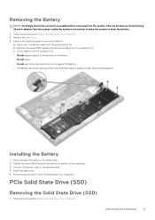
... procedures in the battery bay. 2. Install the base cover. 5. This can be removed within the constraints above, please contact Dell technical support Installing the Battery 1. Connect the battery cable to the computer. 3. PCIe Solid State Drive (SSD) Removing the Solid State Drive (SSD) 1. Place and align the battery in Before Working Inside Your Computer. 2. Removing the Battery NOTE: Discharge the battery as much as possible before removing from the system board [1]. b) Remove the seven...
... procedures in the battery bay. 2. Install the base cover. 5. This can be removed within the constraints above, please contact Dell technical support Installing the Battery 1. Connect the battery cable to the computer. 3. PCIe Solid State Drive (SSD) Removing the Solid State Drive (SSD) 1. Place and align the battery in Before Working Inside Your Computer. 2. Removing the Battery NOTE: Discharge the battery as much as possible before removing from the system board [1]. b) Remove the seven...
Owners Manual
Page 14
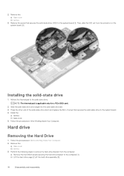
... to remove the hard-drive bracket from its connector on the system board [2]. Press the other end of the solid-state drive down and replace the M2 x 3 screw that secures the solid-state drive (SSD) to the system board. 4. Install the: a) battery b) base cover 5. Follow the procedures in Before Working Inside Your Computer. 2. Installing the solid-state drive 1. b) Lift the hard-drive cage [2] off the hard drive assembly [3]. 14 Disassembly and...
... to remove the hard-drive bracket from its connector on the system board [2]. Press the other end of the solid-state drive down and replace the M2 x 3 screw that secures the solid-state drive (SSD) to the system board. 4. Install the: a) battery b) base cover 5. Follow the procedures in Before Working Inside Your Computer. 2. Installing the solid-state drive 1. b) Lift the hard-drive cage [2] off the hard drive assembly [3]. 14 Disassembly and...
Owners Manual
Page 15
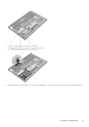
Disconnect the hard drive interposer from the hard drive assembly and then remove the hard drive covers away from the system board [1]. b) Lift the hard drive off the palm rest assembly [2]. 5. Perform the following steps to remove the hard-drive: a) Disconnect the hard-drive cable from the hard drive. Disassembly and reassembly 15 4.
Disconnect the hard drive interposer from the hard drive assembly and then remove the hard drive covers away from the system board [1]. b) Lift the hard drive off the palm rest assembly [2]. 5. Perform the following steps to remove the hard-drive: a) Disconnect the hard-drive cable from the hard drive. Disassembly and reassembly 15 4.
Owners Manual
Page 16
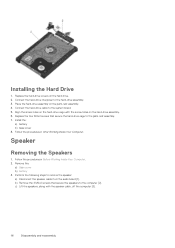
... on the hard drive. 2. Replace the four M2x4 screws that secure the speakers to remove the speaker: a) Disconnect the speaker cable from the audio board [1]. Connect the hard-drive interposer to the palm-rest assembly. 7. Remove the: a) Base cover b) battery 3. Place the hard-drive assembly on the palm-rest assembly. 4. Follow the procedures in After Working Inside Your Computer. Installing the Hard Drive 1. Connect the hard-drive cable to the system board. 5. Follow the procedures in Before Working Inside Your...
... on the hard drive. 2. Replace the four M2x4 screws that secure the speakers to remove the speaker: a) Disconnect the speaker cable from the audio board [1]. Connect the hard-drive interposer to the palm-rest assembly. 7. Remove the: a) Base cover b) battery 3. Place the hard-drive assembly on the palm-rest assembly. 4. Follow the procedures in After Working Inside Your Computer. Installing the Hard Drive 1. Connect the hard-drive cable to the system board. 5. Follow the procedures in Before Working Inside Your...

Owners Manual
Page 17
...Install the: a) battery b) base cover 6. Follow the procedures in Before Working Inside Your Computer. Connect the speaker cable to default. Coin-cell battery Removing the Coin-Cell Battery 1. Follow the procedures in After Working Inside Your Computer. Remove the: a) base cover b) battery c) WLAN card d) hard drive e) fans f) heatsink assembly g) memory modules h) system board 3. Route the speaker cables through the routing guides on the palm-rest assembly. 2. CAUTION: Removing the coin-cell battery re-sets the BIOS settings to the system board. 5. Installing the Speakers...
...Install the: a) battery b) base cover 6. Follow the procedures in Before Working Inside Your Computer. Connect the speaker cable to default. Coin-cell battery Removing the Coin-Cell Battery 1. Follow the procedures in After Working Inside Your Computer. Remove the: a) base cover b) battery c) WLAN card d) hard drive e) fans f) heatsink assembly g) memory modules h) system board 3. Route the speaker cables through the routing guides on the palm-rest assembly. 2. CAUTION: Removing the coin-cell battery re-sets the BIOS settings to the system board. 5. Installing the Speakers...
Owners Manual
Page 18
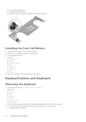
Install the: a) System Board b) Memory c) Heatsink assembly d) Fans e) Hard drive f) WLAN card g) Battery h) Base cover 5. Remove the: a) base cover b) battery c) fans d) heatsink e) SSD f) memory module g) system board 3. a) Lift up the coin cell battery [1] c) Disconnect the coin cell battery cable [2] from the system board [3]. b) Peel back the screw shields [3]. 18 Disassembly and reassembly Replace the coin-cell battery in its slot in Before Working Inside Your Computer. 2. Follow the procedures in the computer. 2. Installing the Coin-Cell Battery 1. Turn the...
Install the: a) System Board b) Memory c) Heatsink assembly d) Fans e) Hard drive f) WLAN card g) Battery h) Base cover 5. Remove the: a) base cover b) battery c) fans d) heatsink e) SSD f) memory module g) system board 3. a) Lift up the coin cell battery [1] c) Disconnect the coin cell battery cable [2] from the system board [3]. b) Peel back the screw shields [3]. 18 Disassembly and reassembly Replace the coin-cell battery in its slot in Before Working Inside Your Computer. 2. Follow the procedures in the computer. 2. Installing the Coin-Cell Battery 1. Turn the...
Owners Manual
Page 31
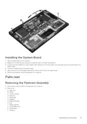
...the procedures in After Working Inside Your Computer. Connect the power-adapter port cable, speaker cable, keyboard-control board cable, touch-pad cable, and touch-screen cable to the system board. 4. Follow the procedures in Before Working Inside Your Computer. 2. Remove the: a) base cover b) battery c) memory modules d) hard drive e) WLAN card f) speakers g) heatsink assembly h) fans i) display assembly j) power adapter port k) system board l) keyboard Disassembly and reassembly 31 Installing the System Board 1. Align the screw hole on the display-cable bracket with the screw...
...the procedures in After Working Inside Your Computer. Connect the power-adapter port cable, speaker cable, keyboard-control board cable, touch-pad cable, and touch-screen cable to the system board. 4. Follow the procedures in Before Working Inside Your Computer. 2. Remove the: a) base cover b) battery c) memory modules d) hard drive e) WLAN card f) speakers g) heatsink assembly h) fans i) display assembly j) power adapter port k) system board l) keyboard Disassembly and reassembly 31 Installing the System Board 1. Align the screw hole on the display-cable bracket with the screw...
Owners Manual
Page 32
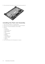
... screws to secure the display hinges to close the display. 4. Press down on the display assembly. 2. Follow the procedures in After Working Inside Your Computer 32 Disassembly and reassembly Align the palm rest assembly on the palm rest assembly to the palm rest assembly. 3. Install the: a) keyboard b) system board c) power connector port d) display assembly e) fans f) heatsink assembly g) speakers h) WLAN card i) hard drive(optional) j) memory modules k) battery l) base cover 5. After performing the above...
... screws to secure the display hinges to close the display. 4. Press down on the display assembly. 2. Follow the procedures in After Working Inside Your Computer 32 Disassembly and reassembly Align the palm rest assembly on the palm rest assembly to the palm rest assembly. 3. Install the: a) keyboard b) system board c) power connector port d) display assembly e) fans f) heatsink assembly g) speakers h) WLAN card i) hard drive(optional) j) memory modules k) battery l) base cover 5. After performing the above...
Owners Manual
Page 33
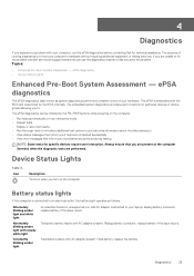
... Lights Enhanced Pre-Boot System Assessment - Battery status lights If the computer is connected to an electrical outlet, the battery light operates as system diagnostics) performs a complete check of running diagnostics is to test your computer's hardware without requiring additional equipment or risking data loss. Temporary battery failure with the BIOS and is embedded with AC adapter present. Diagnostics 33 If you of problems encountered during testing NOTE: Some tests for specific devices...
... Lights Enhanced Pre-Boot System Assessment - Battery status lights If the computer is connected to an electrical outlet, the battery light operates as system diagnostics) performs a complete check of running diagnostics is to test your computer's hardware without requiring additional equipment or risking data loss. Temporary battery failure with the BIOS and is embedded with AC adapter present. Diagnostics 33 If you of problems encountered during testing NOTE: Some tests for specific devices...

Owners Manual
Page 34
... 2 7 display 3 1 RTC power failure 3 2 PCI/Video 3 3 BIOS recovery 1 3 4 BIOS recovery 2 Suggested Resolution processor failure system board, covers BIOS corruption or ROM error no memory/no RAM detected memory failure/RAM failure invalid memory installed system board/ chipset error display failure coin-cell battery failure PCI/Video card/chip failure recovery image nor found recovery image found but invalid 34 Diagnostics Each LED blink takes 0.5 s. The system does not shut down when displaying the Diagnostic Error Codes. Diagnostic Error Codes supersedes any other use of...
... 2 7 display 3 1 RTC power failure 3 2 PCI/Video 3 3 BIOS recovery 1 3 4 BIOS recovery 2 Suggested Resolution processor failure system board, covers BIOS corruption or ROM error no memory/no RAM detected memory failure/RAM failure invalid memory installed system board/ chipset error display failure coin-cell battery failure PCI/Video card/chip failure recovery image nor found recovery image found but invalid 34 Diagnostics Each LED blink takes 0.5 s. The system does not shut down when displaying the Diagnostic Error Codes. Diagnostic Error Codes supersedes any other use of...

Owners Manual
Page 35
... Multi Core Support Intel TurboBoost C-States Control Audio Description Allows you to set the date and time. Table 5. None (Default Setting) Displays the size of keyboard. Displays the asset tag. Displays the size of the HDD. Backlite (Default Setting) Table 6. Displays the product name. Displays the type and size of the extended memory. Enabled (Default Setting) This option enables or disables additional processor sleep states. None (Default Setting) Displays the CPU type. Dell Precision 5520 (Default Setting) Displays the service tag. Displays the CPU speed. Displays the sizes...
... Multi Core Support Intel TurboBoost C-States Control Audio Description Allows you to set the date and time. Table 5. None (Default Setting) Displays the size of keyboard. Displays the asset tag. Displays the size of the HDD. Backlite (Default Setting) Table 6. Displays the product name. Displays the type and size of the extended memory. Enabled (Default Setting) This option enables or disables additional processor sleep states. None (Default Setting) Displays the CPU type. Dell Precision 5520 (Default Setting) Displays the service tag. Displays the CPU speed. Displays the sizes...

Owners Manual
Page 36
... to turn on board devices. Disabled (Default Setting) Table 7. Default Enabled: Enable Boot Support, Enable Thunderbolt Ports; The options are: • External USB Ports - Enable External USB Port This field controls whether the touchscreen is inserted. Function Key (Default Setting) Displays the battery health information. Option Keyboard Illumination USB Configuration Touchscreen AC Behavior Wake On LAN Advanced Battery Charge Configuration Block Sleep Auto On Time Peak Shift USB Wake Support LCD Brightness USB Emulation USB PowerShare USB Wake Support SATA Operation Adapter...
... to turn on board devices. Disabled (Default Setting) Table 7. Default Enabled: Enable Boot Support, Enable Thunderbolt Ports; The options are: • External USB Ports - Enable External USB Port This field controls whether the touchscreen is inserted. Function Key (Default Setting) Displays the battery health information. Option Keyboard Illumination USB Configuration Touchscreen AC Behavior Wake On LAN Advanced Battery Charge Configuration Block Sleep Auto On Time Peak Shift USB Wake Support LCD Brightness USB Emulation USB PowerShare USB Wake Support SATA Operation Adapter...

Owners Manual
Page 37
... system is Enable by the operating system. This option lets you reenable this system allows BIOS updates via hotkeys during POST so that it delete or change , or delete the administrator (admin) password. This option is enabled and visible to set , change any settings you to the operating system. Option Asset Tag Admin Password System Password HDD Password Strong Password Password Change Password Bypass Password configuration Computrace TPM Security UEFI Capsule Firmware Updates CPU XD Support OROM Keyboard Access Table 8.
... system is Enable by the operating system. This option lets you reenable this system allows BIOS updates via hotkeys during POST so that it delete or change , or delete the administrator (admin) password. This option is enabled and visible to set , change any settings you to the operating system. Option Asset Tag Admin Password System Password HDD Password Strong Password Password Change Password Bypass Password configuration Computrace TPM Security UEFI Capsule Firmware Updates CPU XD Support OROM Keyboard Access Table 8.

Owners Manual
Page 38
...System Setup Options Option Load Legacy Option ROM Expert Key Management Intel Software Guard Extensions Set Boot Priority Adapter Warnings SupportAssist OS Recovery Keypad (embedded) Fastboot Extend BIOS POST Time Warnings and Errors Wireless Switch SupportAssist System Resolution Description • Disabled (Default Setting) - Intel Core i7-7700HQ; Enabled (Default Setting) Enables for disables the boot flow for SupportAssist OS Recovery tool in the internal keyboard. This option can be manipulated. WLAN and Bluetooth Enabled (Default Setting) Auto OS Recovery Threshold: Controls...
...System Setup Options Option Load Legacy Option ROM Expert Key Management Intel Software Guard Extensions Set Boot Priority Adapter Warnings SupportAssist OS Recovery Keypad (embedded) Fastboot Extend BIOS POST Time Warnings and Errors Wireless Switch SupportAssist System Resolution Description • Disabled (Default Setting) - Intel Core i7-7700HQ; Enabled (Default Setting) Enables for disables the boot flow for SupportAssist OS Recovery tool in the internal keyboard. This option can be manipulated. WLAN and Bluetooth Enabled (Default Setting) Auto OS Recovery Threshold: Controls...

Quick Start Guide - Windows 7
Page 1
... Windows 7 setup 完成 Windows 7 Windows 7 設定 Windows 7 Windows 7 Set a password for Windows 为 Windows Windows 密碼 Windows Windows Connect to your network NOTE: If you are connecting to a secured wireless network, enter the password for the wireless network access when prompted Protect your computer Product support and manuals Contact Dell 联系 Dell | 連絡 Dell Dell Regulatory and safety Regulatory model Regulatory type Computer model Dell.com/support Dell.com/support/manuals Dell...
... Windows 7 setup 完成 Windows 7 Windows 7 設定 Windows 7 Windows 7 Set a password for Windows 为 Windows Windows 密碼 Windows Windows Connect to your network NOTE: If you are connecting to a secured wireless network, enter the password for the wireless network access when prompted Protect your computer Product support and manuals Contact Dell 联系 Dell | 連絡 Dell Dell Regulatory and safety Regulatory model Regulatory type Computer model Dell.com/support Dell.com/support/manuals Dell...


