
Owners Manual
Page 3
... cover...11 Battery...11 Lithium-ion battery precautions...11 Removing the battery...12 Installing the battery...12 Solid State Drive (SSD)...13 Removing the M.2 Solid State Drive (SSD)...13 Installing the M.2 Solid State Drive (SSD)...13 Hard drive...14 Removing hard drive assembly...14 Installing the hard drive assembly...14 Coin cell battery...15 Removing the coin cell battery...15 Installing the coin...
... cover...11 Battery...11 Lithium-ion battery precautions...11 Removing the battery...12 Installing the battery...12 Solid State Drive (SSD)...13 Removing the M.2 Solid State Drive (SSD)...13 Installing the M.2 Solid State Drive (SSD)...13 Hard drive...14 Removing hard drive assembly...14 Installing the hard drive assembly...14 Coin cell battery...15 Removing the coin cell battery...15 Installing the coin...
Owners Manual
Page 14
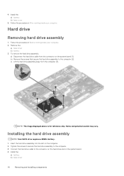
... system board [1]. Tighten the screws to secure the hard drive assembly to the connector on the hard drive and on the system board. 4. Connect the hard drive cable to the computer. 3. Install the: a) battery b) base cover 14 Removing and installing components Follow the procedure in After working inside your computer. 2. 4. Hard drive Removing hard drive assembly 1. NOTE: The image displayed above is...
... system board [1]. Tighten the screws to secure the hard drive assembly to the connector on the hard drive and on the system board. 4. Connect the hard drive cable to the computer. 3. Install the: a) battery b) base cover 14 Removing and installing components Follow the procedure in After working inside your computer. 2. 4. Hard drive Removing hard drive assembly 1. NOTE: The image displayed above is...

Owners Manual
Page 25
...pointstick cable from the connector [ 3, 4, 5, 6]. Place the metal bracket on the computer. 4. Removing and installing components 25 Connect the power connector port cable to the power connector port on the power connector port. ...Removing the chassis frame 1. Follow the procedure in After working inside your computer. 2. Installing the power connector port 1. Insert the power connector port into the slot on the system board. 5. Install the: a) battery b) base cover 6. Remove the: a) SIM card module b) base cover c) battery d) WLAN card e) WWAN card f) SSD card or hard drive...
...pointstick cable from the connector [ 3, 4, 5, 6]. Place the metal bracket on the computer. 4. Removing and installing components 25 Connect the power connector port cable to the power connector port on the power connector port. ...Removing the chassis frame 1. Follow the procedure in After working inside your computer. 2. Installing the power connector port 1. Insert the power connector port into the slot on the system board. 5. Install the: a) battery b) base cover 6. Remove the: a) SIM card module b) base cover c) battery d) WLAN card e) WWAN card f) SSD card or hard drive...

Owners Manual
Page 27
... 1. Place the chassis frame on the system board [3]. Install the: a) SSD card or hard drive b) WWAN card c) WLAN card d) battery e) base cover f) SIM card module 5. Remove the: a) SIM card module b) base cover c) battery d) WLAN card e) WWAN card f) SSD card or hard drive g) memory module h) heat sink assembly i) coin cell battery j) Power connector port k) chassis frame...
... 1. Place the chassis frame on the system board [3]. Install the: a) SSD card or hard drive b) WWAN card c) WLAN card d) battery e) base cover f) SIM card module 5. Remove the: a) SIM card module b) base cover c) battery d) WLAN card e) WWAN card f) SSD card or hard drive g) memory module h) heat sink assembly i) coin cell battery j) Power connector port k) chassis frame...

Owners Manual
Page 30
... cable and metal bracket to system board and tighten the M2.0x3.0 screws to secure to the computer. 3. Remove the: a) base cover b) battery c) WLAN card d) WWAN card e) SSD card or hard drive f) chassis frame 3. SmartCard module Removing the SmartCard reader 1. Follow the procedure in Before working inside your computer. To release the SmartCard reader...
... cable and metal bracket to system board and tighten the M2.0x3.0 screws to secure to the computer. 3. Remove the: a) base cover b) battery c) WLAN card d) WWAN card e) SSD card or hard drive f) chassis frame 3. SmartCard module Removing the SmartCard reader 1. Follow the procedure in Before working inside your computer. To release the SmartCard reader...

Owners Manual
Page 32
... cable to the computer. 3. Place the SmartCard reader on the computer. 2. LED board Removing the LED board 1. Installing the SmartCard reader 1. Remove the: a) base cover b) battery c) WLAN card 32 Removing and installing components Install the: a) chassis frame b) SSD card or hard drive c) WWAN card d) WLAN card e) battery f) base cover 5. Tighten the M2.0x3.0 screws to...
... cable to the computer. 3. Place the SmartCard reader on the computer. 2. LED board Removing the LED board 1. Installing the SmartCard reader 1. Remove the: a) base cover b) battery c) WLAN card 32 Removing and installing components Install the: a) chassis frame b) SSD card or hard drive c) WWAN card d) WLAN card e) battery f) base cover 5. Tighten the M2.0x3.0 screws to...

Owners Manual
Page 33
...chassis frame b) SSD card or hard drive c) WWAN card d) WLAN card e) battery f) base cover 5. c) Lift the LED board away from the connector on the LED board [1]. Connect the LED board cable to the computer [2]. d) WWAN card e) SSD card or hard drive f) chassis frame 3. To remove the LED board: a) Lift ...the latch and disconnect the LED board cable from the computer [3]. b) Remove the M2.0x3.0 screw that secures the LED board to the connector on the ...
...chassis frame b) SSD card or hard drive c) WWAN card d) WLAN card e) battery f) base cover 5. c) Lift the LED board away from the connector on the LED board [1]. Connect the LED board cable to the computer [2]. d) WWAN card e) SSD card or hard drive f) chassis frame 3. To remove the LED board: a) Lift ...the latch and disconnect the LED board cable from the computer [3]. b) Remove the M2.0x3.0 screw that secures the LED board to the connector on the ...

Owners Manual
Page 34
Remove the: a) base cover b) battery c) WLAN card d) WWAN card e) SSD card or hard drive f) chassis frame 3. a) Lift the latch and disconnect the LED board cable [1]. To disconnect the cables: NOTE: Speaker cables are disconnected to remove the chassis frame. b) Disconnect and unroute the speaker cable [2]. 4. Remove the speakers from the computer. 34 Removing and installing components Follow the procedure in Before working inside your computer. 2. Speaker Removing the speaker 1.
Remove the: a) base cover b) battery c) WLAN card d) WWAN card e) SSD card or hard drive f) chassis frame 3. a) Lift the latch and disconnect the LED board cable [1]. To disconnect the cables: NOTE: Speaker cables are disconnected to remove the chassis frame. b) Disconnect and unroute the speaker cable [2]. 4. Remove the speakers from the computer. 34 Removing and installing components Follow the procedure in Before working inside your computer. 2. Speaker Removing the speaker 1.

Owners Manual
Page 35
... hinge cap from the computer [2]. Install the: a) chassis frame b) SSD card or hard drive c) WWAN card d) WLAN card e) battery f) base cover 5. Remove the: a) base cover b) battery 3. Removing and installing components 35 To remove the hinge cap: a) Remove the M2x3.0 (OD4.5) screws that secure the hinge cap to the computer [1]. Connect the speaker and LED board cable...
... hinge cap from the computer [2]. Install the: a) chassis frame b) SSD card or hard drive c) WWAN card d) WLAN card e) battery f) base cover 5. Remove the: a) base cover b) battery 3. Removing and installing components 35 To remove the hinge cap: a) Remove the M2x3.0 (OD4.5) screws that secure the hinge cap to the computer [1]. Connect the speaker and LED board cable...

Owners Manual
Page 47
Remove the: a) base cover b) battery c) keyboard d) WLAN card e) WWAN card f) SSD card or hard drive g) memory module h) heat sink assembly i) coin cell battery j) chassis frame k) system board l) hinge cap m) display assembly NOTE: The component you are left with is the .... Palm rest Replacing the palm rest 1. a) display assembly b) hinge cap c) system board d) chassis frame e) coin cell battery f) heat sink assembly g) memory module h) SSD card or hard drive i) WWAN card Removing and installing components 47
Remove the: a) base cover b) battery c) keyboard d) WLAN card e) WWAN card f) SSD card or hard drive g) memory module h) heat sink assembly i) coin cell battery j) chassis frame k) system board l) hinge cap m) display assembly NOTE: The component you are left with is the .... Palm rest Replacing the palm rest 1. a) display assembly b) hinge cap c) system board d) chassis frame e) coin cell battery f) heat sink assembly g) memory module h) SSD card or hard drive i) WWAN card Removing and installing components 47

Owners Manual
Page 59
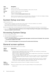
...boot device order and boot directly to a specific device (for example: optical drive or hard drive). The boot sequence screen also displays the option to the previous field. System... Setup screen. 4 System setup options NOTE: Depending on Self Test (POST), when the Dell logo appears. Navigation keys NOTE: For most of the System Setup options, changes that you...menu displays the devices that you make are : • Removable Drive (if available) • STXXXX Drive NOTE: XXX denotes the SATA drive number. • Optical Drive (if available) • Diagnostics NOTE: Choosing Diagnostics, ...
...boot device order and boot directly to a specific device (for example: optical drive or hard drive). The boot sequence screen also displays the option to the previous field. System... Setup screen. 4 System setup options NOTE: Depending on Self Test (POST), when the Dell logo appears. Navigation keys NOTE: For most of the System Setup options, changes that you...menu displays the devices that you make are : • Removable Drive (if available) • STXXXX Drive NOTE: XXX denotes the SATA drive number. • Optical Drive (if available) • Diagnostics NOTE: Choosing Diagnostics, ...
Owners Manual
Page 60
...L2 Cache, Processor L3 Cache, HT Capable, and 64-Bit Technology. • Device Information: Displays Primary Hard Drive, M.2 SATA2, M.2 SATA, M.2 PCIe SSD-0, LOM MAC Address, Video Controller, Video BIOS Version, ... Controller, Wi-Fi Device, WiGig Device, Cellular Device, Bluetooth Device. After the white Dell logo appears, press F2 immediately. Moves to the next field. System Setup overview System Setup...information after you can cause your computer. • Set or change , or remove any unsaved changes and restarts the system. Accessing System Setup 1. Expands or collapses a ...
...L2 Cache, Processor L3 Cache, HT Capable, and 64-Bit Technology. • Device Information: Displays Primary Hard Drive, M.2 SATA2, M.2 SATA, M.2 PCIe SSD-0, LOM MAC Address, Video Controller, Video BIOS Version, ... Controller, Wi-Fi Device, WiGig Device, Cellular Device, Bluetooth Device. After the white Dell logo appears, press F2 immediately. Moves to the next field. System Setup overview System Setup...information after you can cause your computer. • Set or change , or remove any unsaved changes and restarts the system. Accessing System Setup 1. Expands or collapses a ...


