
Quick Start Guide - Windows 7
Page 2
...;口 11. 具备 PowerShare 功能的 USB 3.0 端口 12. HDMI ポート 5. Noble Wedge 10. Camera status light 4. Dual array microphones 8. Battery charge status light 16. Smart Card reader (optional) 19. USB 3.0 port 22. HDMI 포트 5. Nobel Wedge 10. Headset/Microphone 포트 14 15 16...
...;口 11. 具备 PowerShare 功能的 USB 3.0 端口 12. HDMI ポート 5. Noble Wedge 10. Camera status light 4. Dual array microphones 8. Battery charge status light 16. Smart Card reader (optional) 19. USB 3.0 port 22. HDMI 포트 5. Nobel Wedge 10. Headset/Microphone 포트 14 15 16...

Owners Manual
Page 3
... Identification Module (SIM) card 9 Base cover...10 Removing the base cover...10 Installing the base cover...11 Battery...11 Lithium-ion battery precautions...11 Removing the battery...12 Installing the battery...12 Solid State Drive (SSD)...13 Removing the M.2 Solid State Drive (SSD)...13 Installing the M.2 Solid State... Hard drive...14 Removing hard drive assembly...14 Installing the hard drive assembly...14 Coin cell battery...15 Removing the coin cell battery...15 Installing the coin cell battery...15 WLAN card...16 Removing the WLAN card...16 Installing the WLAN card...16 WWAN card...17...
... Identification Module (SIM) card 9 Base cover...10 Removing the base cover...10 Installing the base cover...11 Battery...11 Lithium-ion battery precautions...11 Removing the battery...12 Installing the battery...12 Solid State Drive (SSD)...13 Removing the M.2 Solid State Drive (SSD)...13 Installing the M.2 Solid State... Hard drive...14 Removing hard drive assembly...14 Installing the hard drive assembly...14 Coin cell battery...15 Removing the coin cell battery...15 Installing the coin cell battery...15 WLAN card...16 Removing the WLAN card...16 Installing the WLAN card...16 WWAN card...17...

Owners Manual
Page 6
......74 Port and connector specifications...74 Contactless smart card specifications...75 Contact smart card specifications...75 Display specifications...75 Keyboard specifications...76 Touchpad specifications...76 Battery specifications...76 AC Adapter specifications...77 Physical specifications...77 Environmental specifications...77 6 Diagnostics...79 Enhanced Pre-Boot System Assessment (ePSA) diagnostics 79 Device status lights...
......74 Port and connector specifications...74 Contactless smart card specifications...75 Contact smart card specifications...75 Display specifications...75 Keyboard specifications...76 Touchpad specifications...76 Battery specifications...76 AC Adapter specifications...77 Physical specifications...77 Environmental specifications...77 6 Diagnostics...79 Enhanced Pre-Boot System Assessment (ePSA) diagnostics 79 Device status lights...
Owners Manual
Page 8
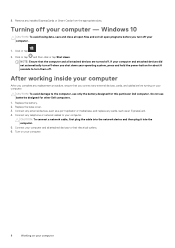
...Turn on your computer. 8 Working on your operating system, press and hold the power button for about 6 seconds to the computer, use batteries designed for this particular Dell computer. Replace the battery. 2. CAUTION: To connect a network cable, first plug the cable into the network device and then plug it into the computer. 5. ...CAUTION: To avoid damage to turn off when you shut down . Do not use only the battery designed for other Dell computers. 1. Connect your computer and all attached devices are turned off your computer
...Turn on your computer. 8 Working on your operating system, press and hold the power button for about 6 seconds to the computer, use batteries designed for this particular Dell computer. Replace the battery. 2. CAUTION: To connect a network cable, first plug the cable into the network device and then plug it into the computer. 5. ...CAUTION: To avoid damage to turn off when you shut down . Do not use only the battery designed for other Dell computers. 1. Connect your computer and all attached devices are turned off your computer

Owners Manual
Page 11
... the base cover 1. Contact https:// www.dell.com/support for assistance and further instructions. • Always purchase genuine batteries from the system to allow the battery to drain. • Do not crush, drop, mutilate, or penetrate the battery with the screw holders on or against the battery. • If a battery gets stuck in After working inside...
... the base cover 1. Contact https:// www.dell.com/support for assistance and further instructions. • Always purchase genuine batteries from the system to allow the battery to drain. • Do not crush, drop, mutilate, or penetrate the battery with the screw holders on or against the battery. • If a battery gets stuck in After working inside...

Owners Manual
Page 12
... components Follow the procedure in After working inside your computer. 2. Insert the battery into the slot on the battery. 3. b) Loosen the M2x5 screws that secure the battery to the computer. 4. Installing the battery NOTE: the 92Whr battery requires the use of a M.2 card and a 68Whr battery can use either a M.2 or 7mm SATA drive. 1. Install the base cover...
... components Follow the procedure in After working inside your computer. 2. Insert the battery into the slot on the battery. 3. b) Loosen the M2x5 screws that secure the battery to the computer. 4. Installing the battery NOTE: the 92Whr battery requires the use of a M.2 card and a 68Whr battery can use either a M.2 or 7mm SATA drive. 1. Install the base cover...

Owners Manual
Page 13
NOTE: For models shipped with NVMe SSDs, remove the thermal plate placed over it. Remove the: a) base cover b) battery 3. Installing the M.2 Solid State Drive (SSD) NOTE: Before installing SSD card, you must make sure that is placed above the SSD card. b) Remove... thermal plate over the SSD. Affix the adhesive tape above the SSD card [1]. Follow the procedure in Before working inside your computer has a 92 Whr battery. 1. c) Slide and lift the SSD from the computer [3]. Insert the SSD into the connector on the computer. 2. Removing and installing components 13 Tighten ...
NOTE: For models shipped with NVMe SSDs, remove the thermal plate placed over it. Remove the: a) base cover b) battery 3. Installing the M.2 Solid State Drive (SSD) NOTE: Before installing SSD card, you must make sure that is placed above the SSD card. b) Remove... thermal plate over the SSD. Affix the adhesive tape above the SSD card [1]. Follow the procedure in Before working inside your computer has a 92 Whr battery. 1. c) Slide and lift the SSD from the computer [3]. Insert the SSD into the connector on the computer. 2. Removing and installing components 13 Tighten ...
Owners Manual
Page 14
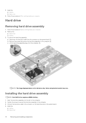
... slot on the system board [1]. Connect the hard drive cable to the connector on the hard drive and on the system board. 4. Install the: a) battery b) base cover 14 Removing and installing components Install the: a) battery b) base cover 5. Remove the: a) base cover b) battery 3. Installing the hard drive assembly NOTE: 7mm SATA drive requires a 68Whr...
... slot on the system board [1]. Connect the hard drive cable to the connector on the hard drive and on the system board. 4. Install the: a) battery b) base cover 14 Removing and installing components Install the: a) battery b) base cover 5. Remove the: a) base cover b) battery 3. Installing the hard drive assembly NOTE: 7mm SATA drive requires a 68Whr...

Owners Manual
Page 15
... After working inside your computer. 2. Remove the: a) base cover b) battery 3. NOTE: Ensure the coin cell battery cable is properly routed to avoid damages to the connector on the system board. 5. b) Pry the coin cell battery to release from the adhesive and lift it away from the connector on ...the system board. 2. Place the coin cell battery into the slot on the system board [1]. Removing and installing components 15 Follow...
... After working inside your computer. 2. Remove the: a) base cover b) battery 3. NOTE: Ensure the coin cell battery cable is properly routed to avoid damages to the connector on the system board. 5. b) Pry the coin cell battery to release from the adhesive and lift it away from the connector on ...the system board. 2. Place the coin cell battery into the slot on the system board [1]. Removing and installing components 15 Follow...

Owners Manual
Page 16
...the computer [1]. To remove the WLAN card: a) Remove the M2.0x3.0 screw that secures the WLAN cables [2]. Remove the: a) base cover b) battery 3. Insert the WLAN card into the slot on the WLAN Card. 4. c) Disconnect the WLAN cables from the adhesive[4]. d) Lift the WLAN card ...to the connectors on the computer. 2. Route the WLAN cables through the routing channel. 3. Install the: a) battery b) base cover 16 Removing and installing components b) Remove the metal tab that secures the WLAN card to the computer. 5. Follow the procedure in...
...the computer [1]. To remove the WLAN card: a) Remove the M2.0x3.0 screw that secures the WLAN cables [2]. Remove the: a) base cover b) battery 3. Insert the WLAN card into the slot on the WLAN Card. 4. c) Disconnect the WLAN cables from the adhesive[4]. d) Lift the WLAN card ...to the connectors on the computer. 2. Route the WLAN cables through the routing channel. 3. Install the: a) battery b) base cover 16 Removing and installing components b) Remove the metal tab that secures the WLAN card to the computer. 5. Follow the procedure in...

Owners Manual
Page 17
... Remove the M2.0x3.0 screw that secures the WWAN card to the connectors on the WWAN Card. 4. Remove the: a) base cover b) battery 3. To remove the WWAN card: a) Disconnect the WWAN cables from the connector[3]. c) Lift the WWAN card away from the connectors [1]. Installing... the WWAN card 1. Install the: a) battery b) base cover 5. Connect the WWAN cables to the computer [2]. Follow the procedure in After working inside your system. Removing and installing ...
... Remove the M2.0x3.0 screw that secures the WWAN card to the connectors on the WWAN Card. 4. Remove the: a) base cover b) battery 3. To remove the WWAN card: a) Disconnect the WWAN cables from the connector[3]. c) Lift the WWAN card away from the connectors [1]. Installing... the WWAN card 1. Install the: a) battery b) base cover 5. Connect the WWAN cables to the computer [2]. Follow the procedure in After working inside your system. Removing and installing ...

Owners Manual
Page 18
... memory module until the clips secure the memory module. 2. Installing the memory module 1. b) Lift the memory module away from the connector [2]. Remove the: a) base cover b) battery 3. Install the: a) battery b) base cover 3. Follow the procedure in After working inside your computer. 2.
... memory module until the clips secure the memory module. 2. Installing the memory module 1. b) Lift the memory module away from the connector [2]. Remove the: a) base cover b) battery 3. Install the: a) battery b) base cover 3. Follow the procedure in After working inside your computer. 2.

Owners Manual
Page 19
... the latch, and disconnect the keyboard cable [1], touchpad cable [2], trackstick cable [3] and back light(optional) [4] from the connector. Removing the keyboard 1. Remove the: a) base cover b) battery c) keyboard trim 3. Keyboard Removing the keyboard trim 1.
... the latch, and disconnect the keyboard cable [1], touchpad cable [2], trackstick cable [3] and back light(optional) [4] from the connector. Removing the keyboard 1. Remove the: a) base cover b) battery c) keyboard trim 3. Keyboard Removing the keyboard trim 1.

Owners Manual
Page 22
... inside your system. Follow the procedure in After working inside your system. Follow the procedure in After working inside your computer. 2. Install the: a) keyboard trim b) battery c) base cover 5.
... inside your system. Follow the procedure in After working inside your system. Follow the procedure in After working inside your computer. 2. Install the: a) keyboard trim b) battery c) base cover 5.

Owners Manual
Page 23
b) Remove the M2.0x3.0 screws that secure the heat sink assembly on the system board[2]. c) Lift the heat sink assembly away from the system board [2]. To remove the heat sink assembly: a) Disconnect the heat sink assembly cable[1] and remove the screws that secure the heat sink assembly to the system board in the order of the callouts shown on the heat sink assembly [1, 2, 3, 4, 5, 6]. b) battery 3. NOTE: Remove the screws that secure on the system board [1]. Removing and installing components 23
b) Remove the M2.0x3.0 screws that secure the heat sink assembly on the system board[2]. c) Lift the heat sink assembly away from the system board [2]. To remove the heat sink assembly: a) Disconnect the heat sink assembly cable[1] and remove the screws that secure the heat sink assembly to the system board in the order of the callouts shown on the heat sink assembly [1, 2, 3, 4, 5, 6]. b) battery 3. NOTE: Remove the screws that secure on the system board [1]. Removing and installing components 23

Owners Manual
Page 24
... the M2.0x3.0 screws to secure the heat sink assembly to release the metal bracket that secures the power connector port [3]. Remove the: a) base cover b) battery 3. b) Remove the M2.0x3.0 screw to the system board. Place the heat sink assembly on the system board in the order of the callout numbers...
... the M2.0x3.0 screws to secure the heat sink assembly to release the metal bracket that secures the power connector port [3]. Remove the: a) base cover b) battery 3. b) Remove the M2.0x3.0 screw to the system board. Place the heat sink assembly on the system board in the order of the callout numbers...

Owners Manual
Page 25
... computer. 2. Chassis frame Removing the chassis frame 1. Follow the procedure in After working inside your computer. 2. Remove the: a) SIM card module b) base cover c) battery d) WLAN card e) WWAN card f) SSD card or hard drive 3. b) Disconnect the speaker cable from the connector on the computer. 4. Removing and installing components 25 ...connector port cable to the power connector port on the system board [2]. Follow the procedure in Before working inside your computer. Install the: a) battery b) base cover 6. Place the metal bracket on the power connector port. 3.
... computer. 2. Chassis frame Removing the chassis frame 1. Follow the procedure in After working inside your computer. 2. Remove the: a) SIM card module b) base cover c) battery d) WLAN card e) WWAN card f) SSD card or hard drive 3. b) Disconnect the speaker cable from the connector on the computer. 4. Removing and installing components 25 ...connector port cable to the power connector port on the system board [2]. Follow the procedure in Before working inside your computer. Install the: a) battery b) base cover 6. Place the metal bracket on the power connector port. 3.

Owners Manual
Page 27
...to avoid damages to the cable. 4. Remove the: a) SIM card module b) base cover c) battery d) WLAN card e) WWAN card f) SSD card or hard drive g) memory module h) heat sink assembly i) coin cell battery j) Power connector port k) chassis frame 3. To release the system board: a) Remove the M2.0x3....0 screws that secures the display cable [2]. Install the: a) SSD card or hard drive b) WWAN card c) WLAN card d) battery e) base cover f) SIM card module 5. Removing and installing components 27 Place the chassis frame on the system board [3]. System board Removing the system ...
...to avoid damages to the cable. 4. Remove the: a) SIM card module b) base cover c) battery d) WLAN card e) WWAN card f) SSD card or hard drive g) memory module h) heat sink assembly i) coin cell battery j) Power connector port k) chassis frame 3. To release the system board: a) Remove the M2.0x3....0 screws that secures the display cable [2]. Install the: a) SSD card or hard drive b) WWAN card c) WLAN card d) battery e) base cover f) SIM card module 5. Removing and installing components 27 Place the chassis frame on the system board [3]. System board Removing the system ...

Owners Manual
Page 30
... on the system board. Installing the system board 1. Install the: a) chassis frame b) coin cell battery c) heat sink assembly d) memory module e) SSD card or hard drive f) WWAN card g) WLAN card h) battery i) base cover j) SIM card module 9. Remove the: a) base cover b) battery c) WLAN card d) WWAN card e) SSD card or hard drive f) chassis frame 3. Place the...
... on the system board. Installing the system board 1. Install the: a) chassis frame b) coin cell battery c) heat sink assembly d) memory module e) SSD card or hard drive f) WWAN card g) WLAN card h) battery i) base cover j) SIM card module 9. Remove the: a) base cover b) battery c) WLAN card d) WWAN card e) SSD card or hard drive f) chassis frame 3. Place the...

Owners Manual
Page 32
Affix the SmartCard reader cable and connect the cable to the computer. 3. Remove the: a) base cover b) battery c) WLAN card 32 Removing and installing components Follow the procedure in After working inside your computer. 2. Follow the procedure in Before... working inside your computer. Install the: a) chassis frame b) SSD card or hard drive c) WWAN card d) WLAN card e) battery f) base cover 5. Installing the SmartCard reader 1. Place the SmartCard reader on the computer. 2. Tighten the M2.0x3.0 screws to secure the SmartCard reader to...
Affix the SmartCard reader cable and connect the cable to the computer. 3. Remove the: a) base cover b) battery c) WLAN card 32 Removing and installing components Follow the procedure in After working inside your computer. 2. Follow the procedure in Before... working inside your computer. Install the: a) chassis frame b) SSD card or hard drive c) WWAN card d) WLAN card e) battery f) base cover 5. Installing the SmartCard reader 1. Place the SmartCard reader on the computer. 2. Tighten the M2.0x3.0 screws to secure the SmartCard reader to...


