
Getting Started Guide
Page 5
Installation and Configuration WARNING: Before performing the following the safety instructions and the rack installation instructions provided with the system. Installing the Rails and System in a Rack Assemble the rails and install the system in the rack following procedure, review the safety instructions that came with your system and identify each item. Unpacking the System Unpack your system. Getting Started With Your System 3
Installation and Configuration WARNING: Before performing the following the safety instructions and the rack installation instructions provided with the system. Installing the Rails and System in a Rack Assemble the rails and install the system in the rack following procedure, review the safety instructions that came with your system and identify each item. Unpacking the System Unpack your system. Getting Started With Your System 3

Getting Started Guide
Page 9
... your system, including those pertaining to troubleshoot the system and install or replace system components. NOTE: Always check for updates on support.dell.com/manuals and read the updates first because they often supersede information in all locations. Getting Started With Your System 7 Obtaining Technical ... that shipped with your system. Warranty information may not be included within this guide or if the system does not perform as a separate document. • The rack documentation included with your system that provides documentation and tools for more information.
... your system, including those pertaining to troubleshoot the system and install or replace system components. NOTE: Always check for updates on support.dell.com/manuals and read the updates first because they often supersede information in all locations. Getting Started With Your System 7 Obtaining Technical ... that shipped with your system. Warranty information may not be included within this guide or if the system does not perform as a separate document. • The rack documentation included with your system that provides documentation and tools for more information.

Hardware Owner's Manual
Page 13
... is on. The ports are USB 2.0-complaint. NOTE: On ACPI-compliant operating systems, turning off the system using the power button causes the system to perform a graceful shutdown before power to troubleshoot software and device driver errors when using the end of memory installed in the system. Connects a monitor to navigate...
... is on. The ports are USB 2.0-complaint. NOTE: On ACPI-compliant operating systems, turning off the system using the power button causes the system to perform a graceful shutdown before power to troubleshoot software and device driver errors when using the end of memory installed in the system. Connects a monitor to navigate...

Hardware Owner's Manual
Page 22
... If a system error occurs, the LCD screen will lose the event history for at 1000 Mbps. For other faults, you will turn amber. You can perform this task remotely, but you must take action to view the list of brief text messages that sensor returns to a normal state. NOTE: The following...
... If a system error occurs, the LCD screen will lose the event history for at 1000 Mbps. For other faults, you will turn amber. You can perform this task remotely, but you must take action to view the list of brief text messages that sensor returns to a normal state. NOTE: The following...

Hardware Owner's Manual
Page 35
... the SEL. Table 1-1. Check the SEL for more power than what the power supply can provide, but it can provide. Check PSU and config. W1628 Performance degraded. NOTE: For the full name of sustained charge. Review & clear log. W1627 Power required > PSU wattage. Turn off power to the system for details...
... the SEL. Table 1-1. Check the SEL for more power than what the power supply can provide, but it can provide. Check PSU and config. W1628 Performance degraded. NOTE: For the full name of sustained charge. Review & clear log. W1627 Power required > PSU wattage. Turn off power to the system for details...

Hardware Owner's Manual
Page 49
... Services image. The iDRAC6 Enterprise card Restore the flash memory flash memory may be using the latest version on performing a field replacement of the flash memory. Unexpected interrupt in the specified slots. or processor combination. Invalid memory configuration... Configuration user documentation for instructions on corrupted. See "Troubleshooting System Memory." Memory modules are installed in a valid configuration. support.dell.com. See the iDRAC6 user's guide for more information. About Your System 49 See "Processors." See "General Memory Module ...
... Services image. The iDRAC6 Enterprise card Restore the flash memory flash memory may be using the latest version on performing a field replacement of the flash memory. Unexpected interrupt in the specified slots. or processor combination. Invalid memory configuration... Configuration user documentation for instructions on corrupted. See "Troubleshooting System Memory." Memory modules are installed in a valid configuration. support.dell.com. See the iDRAC6 user's guide for more information. About Your System 49 See "Processors." See "General Memory Module ...

Hardware Owner's Manual
Page 51
... any system components required exceeds processor(s), memory were just upgraded, return PSU wattage. Check PSU. Warning! modules, and expansion the system to meet PSU wattage. Performance degraded. The memory configuration is : Invalid memory configuration. If the system system by the power supplies. CPU and memory set to minimum frequencies to the...
... any system components required exceeds processor(s), memory were just upgraded, return PSU wattage. Check PSU. Warning! modules, and expansion the system to meet PSU wattage. Performance degraded. The memory configuration is : Invalid memory configuration. If the system system by the power supplies. CPU and memory set to minimum frequencies to the...
Hardware Owner's Manual
Page 55
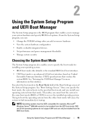
... : • Change the NVRAM settings after you add or remove hardware • View the system hardware configuration • Enable or disable integrated devices • Set performance and power management thresholds • Manage system security Choosing the System Boot Mode The System Setup program also enables you can only be installed from...
... : • Change the NVRAM settings after you add or remove hardware • View the system hardware configuration • Enable or disable integrated devices • Set performance and power management thresholds • Manage system security Choosing the System Boot Mode The System Setup program also enables you can only be installed from...

Hardware Owner's Manual
Page 59
... press to continue or to observe events that may scroll by unnoticed during POST. Video Memory Displays the amount of each other for improved memory performance. System Memory Testing Specifies whether system memory tests are Enabled and Disabled. CAUTION: When setting this field is Enabled, memory interleaving is supported if a symmetric...
... press to continue or to observe events that may scroll by unnoticed during POST. Video Memory Displays the amount of each other for improved memory performance. System Memory Testing Specifies whether system memory tests are Enabled and Disabled. CAUTION: When setting this field is Enabled, memory interleaving is supported if a symmetric...

Hardware Owner's Manual
Page 65
... you select Custom, you can configure each option independently. Power Management Screen Option Power Management CPU Power and Performance Management Fan Power and Performance Management Memory Power and Performance Management Description Options are Maximum Performance or Minimum Power. In this screen as follows: • OS Control sets the CPU power to OS DBPM, the...
... you select Custom, you can configure each option independently. Power Management Screen Option Power Management CPU Power and Performance Management Fan Power and Performance Management Memory Power and Performance Management Description Options are Maximum Performance or Minimum Power. In this screen as follows: • OS Control sets the CPU power to OS DBPM, the...

Hardware Owner's Manual
Page 67
... system to the operating system and results in the TPM. This option prevents booting to remain off . On an ACPI-compliant operating system, the system performs an orderly shutdown before power is turned off after power is restored. Enables or disables the NMI feature.
... system to the operating system and results in the TPM. This option prevents booting to remain off . On an ACPI-compliant operating system, the system performs an orderly shutdown before power is turned off after power is restored. Enables or disables the NMI feature.
Hardware Owner's Manual
Page 73
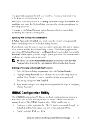
.... The next time you enter the System Setup program, the system prompts you verify the password, the Setup Password changes to assign a new setup password, perform the steps in "Assigning a Setup Password." NOTE: You can assign a system password. Deleting or Changing an Existing Setup Password 1 Enter the System Setup program and...
.... The next time you enter the System Setup program, the system prompts you verify the password, the Setup Password changes to assign a new setup password, perform the steps in "Assigning a Setup Password." NOTE: You can assign a system password. Deleting or Changing an Existing Setup Password 1 Enter the System Setup program and...

Hardware Owner's Manual
Page 75
... came with the product. Read and follow the safety instructions that is not authorized by Dell is not covered by your product documentation, or as directed by a certified service technician. Installing System Components 75 You should only perform troubleshooting and simple repairs as authorized in your warranty. Damage due to the system...
... came with the product. Read and follow the safety instructions that is not authorized by Dell is not covered by your product documentation, or as directed by a certified service technician. Installing System Components 75 You should only perform troubleshooting and simple repairs as authorized in your warranty. Damage due to the system...

Hardware Owner's Manual
Page 78
... back. See Figure 3-3. 3 Push down the latch to servicing that came with the product. Read and follow the safety instructions that is not authorized by Dell is not covered by the online or telephone service and support team. Closing the System 1 Lift up on the latch on top of the bezel... documentation, or as a cooling fan or power supply, turn off the system and attached peripherals, and disconnect the system from the system. You should only perform troubleshooting and simple repairs as authorized in a clockwise direction to engage the latch.
... back. See Figure 3-3. 3 Push down the latch to servicing that came with the product. Read and follow the safety instructions that is not authorized by Dell is not covered by the online or telephone service and support team. Closing the System 1 Lift up on the latch on top of the bezel... documentation, or as a cooling fan or power supply, turn off the system and attached peripherals, and disconnect the system from the system. You should only perform troubleshooting and simple repairs as authorized in a clockwise direction to engage the latch.

Hardware Owner's Manual
Page 87
...be installed in the second power supply bay in the bay by a certified service technician. Damage due to servicing that is not authorized by Dell is functioning properly (see Figure 1-5). Read and follow the safety instructions that the power supply is not covered by the online or telephone ...supply blank must be done by pulling outward on the chassis, then lower the opposite edge of the card into place. You should only perform troubleshooting and simple repairs as directed by your warranty. Installing the Power Supply Blank NOTE: Install the power supply blank only in your ...
...be installed in the second power supply bay in the bay by a certified service technician. Damage due to servicing that is not authorized by Dell is functioning properly (see Figure 1-5). Read and follow the safety instructions that the power supply is not covered by the online or telephone ...supply blank must be done by pulling outward on the chassis, then lower the opposite edge of the card into place. You should only perform troubleshooting and simple repairs as directed by your warranty. Installing the Power Supply Blank NOTE: Install the power supply blank only in your ...

Hardware Owner's Manual
Page 89
... a certified service technician. See "Closing the System." 6 Reconnect the system and peripherals to servicing that is not authorized by Dell is not covered by Dell is enabled in the System Setup program. Read and follow the safety instructions that came with the product. 1 Turn off the... See Figure 3-9. 5 Close the system. Damage due to the chassis, then lift the tray out of the chassis. You should only perform troubleshooting and simple repairs as authorized in your product documentation, or as directed by the online or telephone service and support team. See "...
... a certified service technician. See "Closing the System." 6 Reconnect the system and peripherals to servicing that is not authorized by Dell is not covered by Dell is enabled in the System Setup program. Read and follow the safety instructions that came with the product. 1 Turn off the... See Figure 3-9. 5 Close the system. Damage due to the chassis, then lift the tray out of the chassis. You should only perform troubleshooting and simple repairs as authorized in your product documentation, or as directed by the online or telephone service and support team. See "...
Hardware Owner's Manual
Page 90
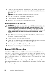
Removing the Internal SD Flash Card CAUTION: Many repairs may only be used as directed by a certified service technician. You should only perform troubleshooting and simple repairs as authorized in your product documentation, or as a boot device, security key, or mass storage device. See "Closing the System."...Locate the SD card connector on the card to release it into the slot. Read and follow the safety instructions that is not authorized by Dell is keyed to ensure correct insertion of the card. 4 Press the card into the card slot to power and restart the system. Internal USB...
Removing the Internal SD Flash Card CAUTION: Many repairs may only be used as directed by a certified service technician. You should only perform troubleshooting and simple repairs as authorized in your product documentation, or as a boot device, security key, or mass storage device. See "Closing the System."...Locate the SD card connector on the card to release it into the slot. Read and follow the safety instructions that is not authorized by Dell is keyed to ensure correct insertion of the card. 4 Press the card into the card slot to power and restart the system. Internal USB...

Hardware Owner's Manual
Page 91
...3 Locate the USB connector on the control panel. See Figure 3-10. 4 Insert the USB memory key into the USB connector. You should only perform troubleshooting and simple repairs as authorized in ) tall. 1 Turn off the system, including any attached peripherals, and disconnect the system from the electrical ..., 79-mm (3.11-in) long, and 8.6-mm (.33-in your warranty. Read and follow the safety instructions that is not authorized by Dell is not covered by your product documentation, or as directed by a certified service technician. Damage due to power and restart the system. See ...
...3 Locate the USB connector on the control panel. See Figure 3-10. 4 Insert the USB memory key into the USB connector. You should only perform troubleshooting and simple repairs as authorized in ) tall. 1 Turn off the system, including any attached peripherals, and disconnect the system from the electrical ..., 79-mm (3.11-in) long, and 8.6-mm (.33-in your warranty. Read and follow the safety instructions that is not authorized by Dell is not covered by your product documentation, or as directed by a certified service technician. Damage due to power and restart the system. See ...

Hardware Owner's Manual
Page 93
...is fully seated, the plastic standoffs snap over the edge of the connector. See Figure 3-11. iDRAC6 Enterprise Card (Optional) The optional Integrated Dell™ Remote Access Controller 6 (iDRAC6) Enterprise card provides a set of advanced features for the port location. 4 If installed, remove all expansion... system board. See "Removing an Expansion Card." 5 Install the iDRAC6 Enterprise card: a Angle the card so that is not authorized by Dell is fully seated. c Press the card down until it is not covered by your product documentation, or as authorized in expansion-card riser ...
...is fully seated, the plastic standoffs snap over the edge of the connector. See Figure 3-11. iDRAC6 Enterprise Card (Optional) The optional Integrated Dell™ Remote Access Controller 6 (iDRAC6) Enterprise card provides a set of advanced features for the port location. 4 If installed, remove all expansion... system board. See "Removing an Expansion Card." 5 Install the iDRAC6 Enterprise card: a Angle the card so that is not authorized by Dell is fully seated. c Press the card down until it is not covered by your product documentation, or as authorized in expansion-card riser ...

Hardware Owner's Manual
Page 94
... (if installed) from expansion-card riser 1. Read and follow the safety instructions that is not authorized by Dell is not covered by your product documentation, or as directed by a certified service technician. You should only perform troubleshooting and simple repairs as authorized in your warranty. See "Opening the System." 3 If installed, remove...
... (if installed) from expansion-card riser 1. Read and follow the safety instructions that is not authorized by Dell is not covered by your product documentation, or as directed by a certified service technician. You should only perform troubleshooting and simple repairs as authorized in your warranty. See "Opening the System." 3 If installed, remove...
