Dell PowerVault 220S Troubleshooting
View Results Below
Free Dell PowerVault 220S manuals!
Problems with Dell PowerVault 220S?
Ask a Question
Free Dell PowerVault 220S manuals!
Problems with Dell PowerVault 220S?
Ask a Question
Related Manual Pages

Similar Questions

Troubleshooting Powervault 114x
"Waiting for target" error How To Access PowerVault Device Dashboard
"Waiting for target" error How To Access PowerVault Device Dashboard
(Posted by satisiwedludlu 7 years ago)
Related Terms
The following terms were also used when searching for Dell PowerVault 220S Troubleshooting:- dell powervault 220s
- dell powervault 220s 221s
- dell powervault 220s array
- dell powervault 220s array manager
- dell powervault 220s beeping
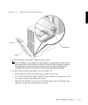
- dell powervault 220s bezel
- dell powervault 220s btu
- dell powervault 220s compatibility matrix
- dell powervault 220s configuration
- dell powervault 220s configuration disk
- dell powervault 220s controller
- dell powervault 220s cost
- dell powervault 220s driver
- dell powervault 220s drivers
- dell powervault 220s drives
- dell powervault 220s drives showing failed
- dell powervault 220s emm
- dell powervault 220s emm firmware download
- dell powervault 220s fan
- dell powervault 220s fibre
- dell powervault 220s fibre card
- dell powervault 220s firmware
- dell powervault 220s hard drive
- dell powervault 220s hard drives
- dell powervault 220s management
- dell powervault 220s manager
- dell powervault 220s manual
- dell powervault 220s manual pdf
- dell powervault 220s parts
- dell powervault 220s parts list
- dell powervault 220s power consumption
- dell powervault 220s power supply
- dell powervault 220s power supply ratings
- dell powervault 220s price
- dell powervault 220s raid
- dell powervault 220s raid requirements
- dell powervault 220s review
- dell powervault 220s sata
- dell powervault 220s scsi
- dell powervault 220s scsi cable
- dell powervault 220s scsi storage array
- dell powervault 220s server
- dell powervault 220s setup
- dell powervault 220s software
- dell powervault 220s specifications
- dell powervault 220s specs
- dell powervault 220s storage array
- dell powervault 220s storage array manual
- dell powervault 220s troubleshooting
- dell powervault 220s u320
- dell powervault 220s update
- dell powervault 220s user guide
- dell powervault 220s visio stencil
- dell powervault 220s visio stencils
- dell powervault 220s weight
- dell powervault 220s/221s
- dell powervault 220s/221s ses
- powervault 220s
- powervault 220s (scsi)
- powervault 220s 146gb disk
- powervault 220s 221s
- powervault 220s 300gb
- powervault 220s and 221s systems
- powervault 220s array
- powervault 220s array manager
- powervault 220s battery
- powervault 220s beeping
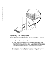
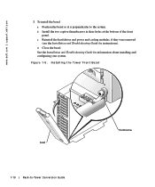
- powervault 220s bezel
- powervault 220s blinking
- powervault 220s btu
- powervault 220s cable
- powervault 220s capacity
- powervault 220s cluster
- powervault 220s cluster mode
- powervault 220s compatibility matrix
- powervault 220s configuration
- powervault 220s configuration disk
- powervault 220s configure raid
- powervault 220s controller
- powervault 220s cost
- powervault 220s dell
- powervault 220s documentation
- powervault 220s driver
- powervault 220s drivers
- powervault 220s drives
- powervault 220s drives showing failed
- powervault 220s emm
- powervault 220s emm firmware download
- powervault 220s fan
- powervault 220s fibre
- powervault 220s fibre card
- powervault 220s firmware
- powervault 220s firmware upgrade
- powervault 220s hard drive
- powervault 220s hard drives
- powervault 220s how configure logical
- powervault 220s how to connect
- powervault 220s how to set up
- powervault 220s install
- powervault 220s management
- powervault 220s management software
- powervault 220s management software iso
- powervault 220s manager
- powervault 220s manual
- powervault 220s manual pdf
- powervault 220s modules
- powervault 220s not recognizing drives
- powervault 220s parts
- powervault 220s parts list
- powervault 220s performance
- powervault 220s power consumption
- powervault 220s power supply
- powervault 220s power supply ratings
- powervault 220s power usage
- powervault 220s price
- powervault 220s rack
- powervault 220s raid
- powervault 220s raid configuration
- powervault 220s raid controller
- powervault 220s raid requirements
- powervault 220s rails
- powervault 220s resource cd
- powervault 220s review
- powervault 220s sata
- powervault 220s scsi
- powervault 220s scsi cable
- powervault 220s scsi storage array
- powervault 220s server
- powervault 220s setup
- powervault 220s software
- powervault 220s spec
- powervault 220s specifications
- powervault 220s specs
- powervault 220s split
- powervault 220s stencil
- powervault 220s storage array
- powervault 220s storage array manual
- powervault 220s troubleshooting
- powervault 220s u320
- powervault 220s u320 emm
- powervault 220s update
- powervault 220s user guide
- powervault 220s visio stencil
- powervault 220s visio stencils
- powervault 220s weight
- powervault 220s windows 2008
- powervault 220s/221s
- powervault 220s/221s ses