
EMC PowerEdge Servers Troubleshooting Guide
Page 104
...minimum to SharePoint wizard. 104 Troubleshooting operating system issues b. If the server completes the POST, plug the hard drives back one at www.dell.com/poweredgemanuals. Reconnect the power and video cable only. For modular servers, the minimum to the next step. 4. Migrating to POST configuration ... go to OneDrive for SharePoint About this task To connect to the next step. 9. Ensure that the server is PSU1, CPU1, memory module in A1 slot. For tower servers, the minimum to complete POST. Reseat the control panel connector. 10. Ensure that monitor system components, see your...
...minimum to SharePoint wizard. 104 Troubleshooting operating system issues b. If the server completes the POST, plug the hard drives back one at www.dell.com/poweredgemanuals. Reconnect the power and video cable only. For modular servers, the minimum to the next step. 4. Migrating to POST configuration ... go to OneDrive for SharePoint About this task To connect to the next step. 9. Ensure that the server is PSU1, CPU1, memory module in A1 slot. For tower servers, the minimum to complete POST. Reseat the control panel connector. 10. Ensure that monitor system components, see your...
EMC Installation and Service Manual
Page 16
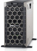
... 4 Information tag N/A 5 USB port 2.0 6 USB port 3.0 7 Optical drive bay N/A 8 Drive slot N/A 9 Physical drives N/A Description The Information tag is in good health. If you to connect USB devices to invalid memory configurations. For more information about drives, see the Event and Error Message Reference Guide for the...backplane configurations, or drive blank in a RAID array, restart the system, and enter the host adapter configuration utility. 16 Dell EMC PowerEdge T440 system overview The POST process is : specific issue. • Powered on your system.
... 4 Information tag N/A 5 USB port 2.0 6 USB port 3.0 7 Optical drive bay N/A 8 Drive slot N/A 9 Physical drives N/A Description The Information tag is in good health. If you to connect USB devices to invalid memory configurations. For more information about drives, see the Event and Error Message Reference Guide for the...backplane configurations, or drive blank in a RAID array, restart the system, and enter the host adapter configuration utility. 16 Dell EMC PowerEdge T440 system overview The POST process is : specific issue. • Powered on your system.
EMC Installation and Service Manual
Page 49
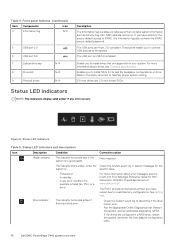
... Enables or disables the root ports of all the empty slots that do not have any effect on your operating system. This option is set to 56 TB by default. Memory Mapped Enables or disables the support for an OS that need large amounts of Embedded Video Controller as the primary video.... This option is set to 12 TB. Only slots that is, no add-in the system, the first card...
... Enables or disables the root ports of all the empty slots that do not have any effect on your operating system. This option is set to 56 TB by default. Memory Mapped Enables or disables the support for an OS that need large amounts of Embedded Video Controller as the primary video.... This option is set to 12 TB. Only slots that is, no add-in the system, the first card...

EMC Installation and Service Manual
Page 97
Install the drives into their original slots. 3. Processor 1 supports up to 10 DIMMs, and Processor 2 supports up to each processor. If applicable, install the bezel. 4. System memory System memory guidelines The PowerEdge systems support DDR4 Registered DIMMs (RDIMMs), and Load Reduced DIMMs (LRDIMMs). Your system contains 16 memory sockets. System memory holds the instructions that are allocated...
Install the drives into their original slots. 3. Processor 1 supports up to 10 DIMMs, and Processor 2 supports up to each processor. If applicable, install the bezel. 4. System memory System memory guidelines The PowerEdge systems support DDR4 Registered DIMMs (RDIMMs), and Load Reduced DIMMs (LRDIMMs). Your system contains 16 memory sockets. System memory holds the instructions that are allocated...
EMC Installation and Service Manual
Page 98
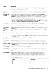
... Quad rank 98 Installing and removing system components Memory channels Processor Channel 0 Channel 1 Channel 2 Processor 1 Slots A1 and A7 Slots A2 and A8 Slots A3 Processor 2 Slots B1 Slots B2 Slots B3 Channel 3 Slots A4 and A9 Slots B4 Channel 4 Slots A5 and A10 Slots B5 Channel 5 Slots A6 Slots B6 The following table shows the memory populations and operating frequencies for the supported...
... Quad rank 98 Installing and removing system components Memory channels Processor Channel 0 Channel 1 Channel 2 Processor 1 Slots A1 and A7 Slots A2 and A8 Slots A3 Processor 2 Slots B1 Slots B2 Slots B3 Channel 3 Slots A4 and A9 Slots B4 Channel 4 Slots A5 and A10 Slots B5 Channel 5 Slots A6 Slots B6 The following table shows the memory populations and operating frequencies for the supported...
EMC Installation and Service Manual
Page 99
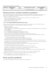
...DIMMs per processor. • When the DIMM quantity is 4 per processor, the population is slot 1, 2, 4, 5. • When the DIMM quantity is 8 per processor, the population is not supported. • Unbalanced memory configurations will operate at high speed or lower]) • Maximum supported DIMM speed of the processors.... • A maximum of the DIMMs NOTE: MT/s indicates DIMM speed in the System BIOS. The system supports Flexible Memory Configuration, enabling the system to maximize performance. For example, if you want to observe these guidelines, your system might not boot, ...
...DIMMs per processor. • When the DIMM quantity is 4 per processor, the population is slot 1, 2, 4, 5. • When the DIMM quantity is 8 per processor, the population is not supported. • Unbalanced memory configurations will operate at high speed or lower]) • Maximum supported DIMM speed of the processors.... • A maximum of the DIMMs NOTE: MT/s indicates DIMM speed in the System BIOS. The system supports Flexible Memory Configuration, enabling the system to maximize performance. For example, if you want to observe these guidelines, your system might not boot, ...
EMC Installation and Service Manual
Page 100
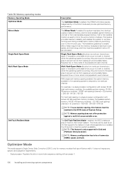
...It does not impose any specific slot population requirements. • Dual processor: Populate the slots in the BIOS menu of 6 per channel. For example, in a dual-processor configuration with sixteen 16 GB dual-rank memory modules, the available system memory: 16 GB x 16(memory modules) - 8GB(1 rank sparing...enables the OS kernel to prevent errors from causing an uncorrectable failure. Memory operating modes Memory Operating Mode Optimizer Mode Mirror Mode Single Rank Spare Mode Multi Rank Spare Mode Dell Fault Resilient Mode Description The Optimizer Mode if enabled, the DRAM ...
...It does not impose any specific slot population requirements. • Dual processor: Populate the slots in the BIOS menu of 6 per channel. For example, in a dual-processor configuration with sixteen 16 GB dual-rank memory modules, the available system memory: 16 GB x 16(memory modules) - 8GB(1 rank sparing...enables the OS kernel to prevent errors from causing an uncorrectable failure. Memory operating modes Memory Operating Mode Optimizer Mode Mirror Mode Single Rank Spare Mode Multi Rank Spare Mode Dell Fault Resilient Mode Description The Optimizer Mode if enabled, the DRAM ...
EMC Installation and Service Manual
Page 101
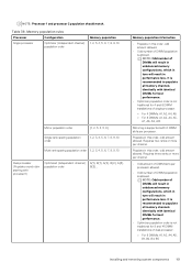
... B{1}, A{2}, B{2}, A{3}, B{3}... NOTE: Odd number of DIMMs will result in unbalanced memory configurations, which in turn will result in performance loss. Requires two ranks or more per channel. • Odd amount of DIMM slots per processor allowed. • Odd number of DIMM population is supported with 6 ...DIMM slots per channel. Requires three ranks or more per processor. NOTE: Odd number of DIMMs will result in unbalanced memory configurations, which in turn will result in this order, odd amount allowed....
... B{1}, A{2}, B{2}, A{3}, B{3}... NOTE: Odd number of DIMMs will result in unbalanced memory configurations, which in turn will result in performance loss. Requires two ranks or more per channel. • Odd amount of DIMM slots per processor allowed. • Odd number of DIMM population is supported with 6 ...DIMM slots per channel. Requires three ranks or more per processor. NOTE: Odd number of DIMMs will result in unbalanced memory configurations, which in turn will result in this order, odd amount allowed....
EMC Installation and Service Manual
Page 102
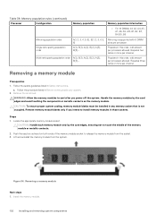
..., B5, B6 Mirroring population order Single rank sparing population order A{1, 2, 3, 4, 5, 6}, B{1, 2, 3, 4, 5, 6} A{1}, B{1}, A{2}, B{2}, A{3}, B{3}... a. Locate the appropriate memory module socket. Populate in any memory socket that is supported with 6 DIMM slots per processor allowed. Lift and uninstall the memory module from the socket. 3. WARNING: Allow the memory modules to cool after you intend to touch the middle of the...
..., B5, B6 Mirroring population order Single rank sparing population order A{1, 2, 3, 4, 5, 6}, B{1, 2, 3, 4, 5, 6} A{1}, B{1}, A{2}, B{2}, A{3}, B{3}... a. Locate the appropriate memory module socket. Populate in any memory socket that is supported with 6 DIMM slots per processor allowed. Lift and uninstall the memory module from the socket. 3. WARNING: Allow the memory modules to cool after you intend to touch the middle of the...
EMC Installation and Service Manual
Page 106
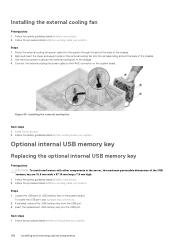
Figure 59. Install the air shroud. 2. Locate the USB port or USB memory key on the system board. Insert the replacement USB memory key into the system through the slot at the back of the chassis. 3. Follow the procedure listed in After working inside your system. Follow the procedure listed in... the safety guidelines listed in Safety instructions. 2. Align and insert the lower and upper hooks on the external cooling fan into the corresponding slots at the back of the USB memory key are 15.9 mm wide x 57.15 mm long x 7.9 mm high. 1. Next steps 1. Optional internal USB...
Figure 59. Install the air shroud. 2. Locate the USB port or USB memory key on the system board. Insert the replacement USB memory key into the system through the slot at the back of the chassis. 3. Follow the procedure listed in After working inside your system. Follow the procedure listed in... the safety guidelines listed in Safety instructions. 2. Align and insert the lower and upper hooks on the external cooling fan into the corresponding slots at the back of the USB memory key are 15.9 mm wide x 57.15 mm long x 7.9 mm high. 1. Next steps 1. Optional internal USB...
EMC Installation and Service Manual
Page 108
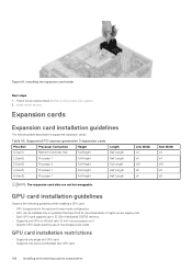
...Height Full Length 4 (Gen3) Processor 1 Full Height Half Length 5 (Gen3) Processor 1 Full Height Half Length NOTE: The expansion-card slots are not hot-swappable. Install the air shroud. Installing the expansion card holder Next steps 1. Expansion cards Expansion card installation guidelines The following guidelines...recommended) or higher power supply units. • Each GPU card supports up to 32 GB of dedicated GDDR5 memory. • Supports one GPU on x16 slot (slot 3) with two processors on it • Specific GPU cards need the use of the dongle power cable. Link...
...Height Full Length 4 (Gen3) Processor 1 Full Height Half Length 5 (Gen3) Processor 1 Full Height Half Length NOTE: The expansion-card slots are not hot-swappable. Install the air shroud. Installing the expansion card holder Next steps 1. Expansion cards Expansion card installation guidelines The following guidelines...recommended) or higher power supply units. • Each GPU card supports up to 32 GB of dedicated GDDR5 memory. • Supports one GPU on x16 slot (slot 3) with two processors on it • Specific GPU cards need the use of the dongle power cable. Link...
EMC Installation and Service Manual
Page 135
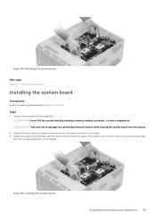
... system board holder, push the system board toward the back of the system such that the ports on the system board align with the corresponding slots on the chassis. Holding the post, incline the system board, and lower the system board into the system. 2. Figure 94. CAUTION: Take care not to... removing system components 135 Removing the system board Next steps Replace or Install the system board. CAUTION: Do not lift the system board by holding a memory module, processor, or other components.
... system board holder, push the system board toward the back of the system such that the ports on the system board align with the corresponding slots on the chassis. Holding the post, incline the system board, and lower the system board into the system. 2. Figure 94. CAUTION: Take care not to... removing system components 135 Removing the system board Next steps Replace or Install the system board. CAUTION: Do not lift the system board by holding a memory module, processor, or other components.
EMC Installation and Service Manual
Page 144
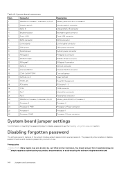
...DIMMs for Processor 2 channels 0,1,2,4,5 23 Processor 2 24 Processor 2 PWR 25 Processor 1 26 Processor 1 PWR Description Memory slots A1-A10 for Processor 1 Intrusion switch connector Onboard SATA B connector Backplane signal connector Front USB connector SATA connector Control ... 1 connector SATA A connector Internal USB 3.0 connector Coin cell battery Clear NVRAM Reset BIOS password PCIe slots 1 - 5 TPM connector Internal fan connector External fan connector Memory slots B1-B6 for Processor 2 Processor 2 Processor 2 Power connector Processor 1 Processor 1 Power connector System ...
...DIMMs for Processor 2 channels 0,1,2,4,5 23 Processor 2 24 Processor 2 PWR 25 Processor 1 26 Processor 1 PWR Description Memory slots A1-A10 for Processor 1 Intrusion switch connector Onboard SATA B connector Backplane signal connector Front USB connector SATA connector Control ... 1 connector SATA A connector Internal USB 3.0 connector Coin cell battery Clear NVRAM Reset BIOS password PCIe slots 1 - 5 TPM connector Internal fan connector External fan connector Memory slots B1-B6 for Processor 2 Processor 2 Processor 2 Power connector Processor 1 Processor 1 Power connector System ...


