PowerEdge T440 - Dell
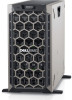
PowerEdge T440
View Results Below
Free Dell PowerEdge T440 manuals!
Problems with Dell PowerEdge T440?
Ask a Question
Free Dell PowerEdge T440 manuals!
Problems with Dell PowerEdge T440?
Ask a Question
Related Manual Pages
Related Videos

Dell Poweredge T440 review
Duration: 7:30
Total Views: 3
Duration: 7:30
Total Views: 3
?ánh giá máy ch? tower Dell PowerEdge T440
Duration: 8:57
Total Views: 463
Duration: 8:57
Total Views: 463
Dell PowerEdge T440 and T130 Servers available from Impress Computers in Houston TX
Duration: 1:55
Total Views: 111
Duration: 1:55
Total Views: 111
Dell PowerEdge T440 Server
Duration: :11
Total Views: 65
Duration: :11
Total Views: 65
Missing Security Bezel in a new Dell PowerEdge T440
Duration: :35
Total Views: 1,088
Duration: :35
Total Views: 1,088
Similar Questions

Flashing Green Light On Raid Controller - Dell Poweredge T105
What is the meaning of the flashing green light on the add-in raid controller of the Dell PowerEdge ...
What is the meaning of the flashing green light on the add-in raid controller of the Dell PowerEdge ...
(Posted by wwilly 9 years ago)

How To Connect Monitor In Dell Poweredge M1000e In M9100 Blade Chasis
how to connect monitor in Dell Poweredge m1000e in m9100 Blade chasis
how to connect monitor in Dell Poweredge m1000e in m9100 Blade chasis
(Posted by pradeepece28 9 years ago)

Can I Run Windows 7 On A Dell Poweredge T100
I have a Dell PowerEdge T100 running Windows 2003 server. I would like to reimage and install Window...
I have a Dell PowerEdge T100 running Windows 2003 server. I would like to reimage and install Window...
(Posted by jaynesample 12 years ago)