
Glossary
Page 1
... system contains an expansion bus that allows the processor to a system, usually by the DMTF. C - CA - Certificate authority. Dell™ Glossary NOTE: For additional information on storage terminology, visit the Storage Networking Industry Association's website at www.snia.org and click...mapping techniques for security or tracking purposes. A - Alternating current. A module that includes power supplies and fans. A CD, diskette, or USB memory key that keeps a copy of CIM data with controllers for developing technology standards in the U.S. bus - A fast storage area that ...
... system contains an expansion bus that allows the processor to a system, usually by the DMTF. C - CA - Certificate authority. Dell™ Glossary NOTE: For additional information on storage terminology, visit the Storage Networking Industry Association's website at www.snia.org and click...mapping techniques for security or tracking purposes. A - Alternating current. A module that includes power supplies and fans. A CD, diskette, or USB memory key that keeps a copy of CIM data with controllers for developing technology standards in the U.S. bus - A fast storage area that ...

Glossary
Page 5
mAh - memory address - memory - A portable flash memory storage device integrated with a USB connector. Megahertz. See also striping and RAID. NAS - NAS systems have their own operating systems, integrated hardware, and software... Control address. MBps - MBR - Megabytes per second. However, when referring to hard-drive capacity, the term is monitored and managed using Dell OpenManage™ Server Administrator. Mirroring functionality is an ASCII file that connects to serve specific storage needs. A small circuit board containing DRAM chips...
mAh - memory address - memory - A portable flash memory storage device integrated with a USB connector. Megahertz. See also striping and RAID. NAS - NAS systems have their own operating systems, integrated hardware, and software... Control address. MBps - MBR - Megabytes per second. However, when referring to hard-drive capacity, the term is monitored and managed using Dell OpenManage™ Server Administrator. Mirroring functionality is an ASCII file that connects to serve specific storage needs. A small circuit board containing DRAM chips...

Glossary
Page 8
...'s integral components, such as the last device at each disk. TCP/IP - A port on a network hub or switch used . USB devices can be configured for operation. SNMP - striping - system configuration information - Some devices (such as the processor(s), RAM, controllers for...engine. A battery-powered unit that allows a network manager to other hubs or switches without requiring a crossover cable. Universal Serial Bus. USB memory key - See memory key. 8 system memory - Because the System Setup program is running. When such devices are video standards ...
...'s integral components, such as the last device at each disk. TCP/IP - A port on a network hub or switch used . USB devices can be configured for operation. SNMP - striping - system configuration information - Some devices (such as the processor(s), RAM, controllers for...engine. A battery-powered unit that allows a network manager to other hubs or switches without requiring a crossover cable. Universal Serial Bus. USB memory key - See memory key. 8 system memory - Because the System Setup program is running. When such devices are video standards ...
Glossary
Page 15
TCP/IP U-DIMM DDR3 UPS USB USB USB USB USB V VAC VDC VGA VGA 和 SVGA W WH WMI - SNMP SVGA VGA 和 SVGA TCP/IP Internet 协议。 TOE - Windows Management Instrumentation 提供 CIM ZIF CPU I/O 9 USB 15
TCP/IP U-DIMM DDR3 UPS USB USB USB USB USB V VAC VDC VGA VGA 和 SVGA W WH WMI - SNMP SVGA VGA 和 SVGA TCP/IP Internet 协议。 TOE - Windows Management Instrumentation 提供 CIM ZIF CPU I/O 9 USB 15

Glossary
Page 48
... graphics array VGA と SVGA TCP/IP - Unregistered DDR3 UPS - Watt-hour WMI - Video graphics array VGA と SVGA W - Watt WH - SMART - Uninterruptible power supply USB - Zero insertion force 48 TCP/IP U-DIMM - Volt direct current VGA - Windows Management Instrumentation。CIM ZIF - Simple Network Management Protocol SVGA - Volts alternating current...
... graphics array VGA と SVGA TCP/IP - Unregistered DDR3 UPS - Watt-hour WMI - Video graphics array VGA と SVGA W - Watt WH - SMART - Uninterruptible power supply USB - Zero insertion force 48 TCP/IP U-DIMM - Volt direct current VGA - Windows Management Instrumentation。CIM ZIF - Simple Network Management Protocol SVGA - Volts alternating current...

Glossary
Page 58
.../IP Transmission Control Protocol/Internet Protocol TOE - TCP/IP TCP/IP Offload Engine U-DIMM DDR3 Unregistered(Unbuffered) DDR3 Memory Module UPS Uninterruptible Power Supply USB Universal Serial Bus USB USB USB USB V - 볼트 (Volt VAC Volt Alternating Current VDC Volt Direct Current VGA Video Graphics Array VGA 와 SVGA W - 와트 (Watt WH Watt...
.../IP Transmission Control Protocol/Internet Protocol TOE - TCP/IP TCP/IP Offload Engine U-DIMM DDR3 Unregistered(Unbuffered) DDR3 Memory Module UPS Uninterruptible Power Supply USB Universal Serial Bus USB USB USB USB V - 볼트 (Volt VAC Volt Alternating Current VDC Volt Direct Current VGA Video Graphics Array VGA 와 SVGA W - 와트 (Watt WH Watt...
Owner's Manual
Page 5
... Cooling Fan...75 Installing The Internal Cooling Fan...77 Removing The External Cooling Fan ...78 Installing The External Cooling Fan...80 Internal USB Memory Key (Optional)...80 Replacing The Internal USB Key...80 PCIe Card Holder (Optional)...82 Removing The PCIe Card Holder...82 Installing The PCIe Card Holder...83 Expansion Cards...
... Cooling Fan...75 Installing The Internal Cooling Fan...77 Removing The External Cooling Fan ...78 Installing The External Cooling Fan...80 Internal USB Memory Key (Optional)...80 Replacing The Internal USB Key...80 PCIe Card Holder (Optional)...82 Removing The PCIe Card Holder...82 Installing The PCIe Card Holder...83 Expansion Cards...

Owner's Manual
Page 7
...And Your System...125 Troubleshooting System Startup Failure...125 Troubleshooting External Connections...125 Troubleshooting The Video Subsystem...125 Troubleshooting A USB Device...125 Troubleshooting A Serial I/O Device...126 Troubleshooting A NIC...126 Troubleshooting A Wet System...126 Troubleshooting A Damaged... A Hard Drive...131 Troubleshooting Expansion Cards...132 Troubleshooting Processor...133 6 Using System Diagnostics...135 Dell Online Diagnostics...135 Dell Embedded System Diagnostics...135 When To Use The Embedded System Diagnostics 135 Running The Embedded System ...
...And Your System...125 Troubleshooting System Startup Failure...125 Troubleshooting External Connections...125 Troubleshooting The Video Subsystem...125 Troubleshooting A USB Device...125 Troubleshooting A Serial I/O Device...126 Troubleshooting A NIC...126 Troubleshooting A Wet System...126 Troubleshooting A Damaged... A Hard Drive...131 Troubleshooting Expansion Cards...132 Troubleshooting Processor...133 6 Using System Diagnostics...135 Dell Online Diagnostics...135 Dell Embedded System Diagnostics...135 When To Use The Embedded System Diagnostics 135 Running The Embedded System ...
Owner's Manual
Page 11
...for more than 15 seconds. Your system supports one of these buttons is connected to locate a particular system within a rack. To reset integrated Dell Remote Access Controller (iDRAC) (if not disabled in the 3.5 inch hard-drive carriers 11 NOTE: If the system is pressed, the LCD ...status indicator on . The LCD lights blue during POST, press and hold for more than five seconds to the system. The ports are USB 2.0-compliant. NOTE: On Advanced Configuration and Power Interface (ACPI)-compliant operating systems, turning off the system using the power button causes the ...
...for more than 15 seconds. Your system supports one of these buttons is connected to locate a particular system within a rack. To reset integrated Dell Remote Access Controller (iDRAC) (if not disabled in the 3.5 inch hard-drive carriers 11 NOTE: If the system is pressed, the LCD ...status indicator on . The LCD lights blue during POST, press and hold for more than five seconds to the system. The ports are USB 2.0-compliant. NOTE: On Advanced Configuration and Power Interface (ACPI)-compliant operating systems, turning off the system using the power button causes the ...
Owner's Manual
Page 13
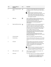
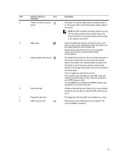
...hold for more than five seconds to locate a particular system within a rack. A slide-out label panel which allows you to connect USB devices to record system information such as Service Tag, NIC, MAC address, and so on. The diagnostic indicators light up to the ...a graceful shutdown before power to the system is turned off. 4 NMI button 5 System identification button 6 Information tag 7 Diagnostic indicators 8 USB connectors (2) Used to troubleshoot software and device driver errors when running certain operating systems. This button can be used to enter BIOS progress mode...
...hold for more than five seconds to locate a particular system within a rack. A slide-out label panel which allows you to connect USB devices to record system information such as Service Tag, NIC, MAC address, and so on. The diagnostic indicators light up to the ...a graceful shutdown before power to the system is turned off. 4 NMI button 5 System identification button 6 Information tag 7 Diagnostic indicators 8 USB connectors (2) Used to troubleshoot software and device driver errors when running certain operating systems. This button can be used to enter BIOS progress mode...
Owner's Manual
Page 15
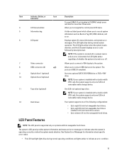
...The LCD lights amber when the system needs attention, and the LCD panel displays an error code followed by descriptive text. The ports are USB 2.0-compliant. The system's LCD panel provides system information and status and error messages to indicate when the system is installed with a double-...information such as Service Tag, NIC, MAC address, and so on or off. 7 Video connector 8 USB connectors (2) 9 Optical drive 1 (optional) 10 Optical drive 2 (optional) Allows you to connect USB devices to two optional SATA DVD-ROM drive or DVD+/-RW drive. See System Error Messages for more ...
...The LCD lights amber when the system needs attention, and the LCD panel displays an error code followed by descriptive text. The ports are USB 2.0-compliant. The system's LCD panel provides system information and status and error messages to indicate when the system is installed with a double-...information such as Service Tag, NIC, MAC address, and so on or off. 7 Video connector 8 USB connectors (2) 9 Optical drive 1 (optional) 10 Optical drive 2 (optional) Allows you to connect USB devices to two optional SATA DVD-ROM drive or DVD+/-RW drive. See System Error Messages for more ...

Owner's Manual
Page 21
.... NOTE: The port is available for use only if the iDRAC7 Enterprise license is installed on and off. The ports are USB 2.0-compliant. Allows you to connect up to locate a particular system within a rack. When one of these buttons is pressed ... backplane. 2 PCIe expansion card slots (5) 3 vFlash media card slot 4 iDRAC7 Enterprise port 5 System identification button 6 System identification connector 7 USB connectors (6) 8 Ethernet connectors (2) 9 Video connector 10 Serial connector 11 External cooling fan power cable slot Allow you to connect a serial device...
.... NOTE: The port is available for use only if the iDRAC7 Enterprise license is installed on and off. The ports are USB 2.0-compliant. Allows you to connect up to locate a particular system within a rack. When one of these buttons is pressed ... backplane. 2 PCIe expansion card slots (5) 3 vFlash media card slot 4 iDRAC7 Enterprise port 5 System identification button 6 System identification connector 7 USB connectors (6) 8 Ethernet connectors (2) 9 Video connector 10 Serial connector 11 External cooling fan power cable slot Allow you to connect a serial device...
Owner's Manual
Page 30
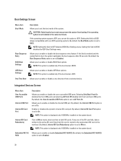
...and the system fails to boot, the system reattempts the boot sequence after 30 seconds. Integrated Devices Screen Menu Item User Accessible USB Ports Internal USB Port Internal SD Card Port Internal SD Card Redundancy Embedded NIC1 & NIC2 Description Allows you to enable or disable Embedded NIC1 &... NIC2. Selecting Only Back Ports On disables the front USB ports and selecting All Ports Off disables both SD cards. Enables or disables the system's internal SD card port. CAUTION: Switching the ...
...and the system fails to boot, the system reattempts the boot sequence after 30 seconds. Integrated Devices Screen Menu Item User Accessible USB Ports Internal USB Port Internal SD Card Port Internal SD Card Redundancy Embedded NIC1 & NIC2 Description Allows you to enable or disable Embedded NIC1 &... NIC2. Selecting Only Back Ports On disables the front USB ports and selecting All Ports Off disables both SD cards. Enables or disables the system's internal SD card port. CAUTION: Switching the ...
Owner's Manual
Page 80
... assembly extending off the system, including any attached peripherals. Close the system. 13. Damage due to servicing that is not authorized by Dell is not covered by your warranty. NOTE: For systems installed with the wheel assembly, ensure that came with the product. NOTE: To... locate the internal USB connector (INT USB) on a flat, stable surface and rotate the system feet outward. 14. You should only perform troubleshooting and simple repairs as authorized...
... assembly extending off the system, including any attached peripherals. Close the system. 13. Damage due to servicing that is not authorized by Dell is not covered by your warranty. NOTE: For systems installed with the wheel assembly, ensure that came with the product. NOTE: To... locate the internal USB connector (INT USB) on a flat, stable surface and rotate the system feet outward. 14. You should only perform troubleshooting and simple repairs as authorized...

Owner's Manual
Page 81
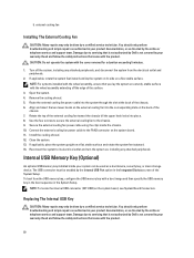
... you lay the system on a sturdy, stable surface with the wheel assembly, ensure that the USB key is detected by the system. Insert the new USB key into the USB connector. 7. 1. USB connector 81 NOTE: For systems installed with the wheel assembly extending off the system, including any attached...the system feet inward and lay the system on its electrical outlet and turn the system on a flat, stable surface. USB key 2. Locate the USB connector (INT USB) or the USB key on a flat, stable surface and rotate the system feet outward. 9. If applicable, place the system upright on ...
... you lay the system on a sturdy, stable surface with the wheel assembly, ensure that the USB key is detected by the system. Insert the new USB key into the USB connector. 7. 1. USB connector 81 NOTE: For systems installed with the wheel assembly extending off the system, including any attached...the system feet inward and lay the system on its electrical outlet and turn the system on a flat, stable surface. USB key 2. Locate the USB connector (INT USB) or the USB key on a flat, stable surface and rotate the system feet outward. 9. If applicable, place the system upright on ...
Owner's Manual
Page 88
... Reconnect the system to the back of the chassis. 6. For more information, see the iDRAC7 User's Guide at support.dell.com/manuals. Remove the screw securing the iDRAC ports card to its electrical outlet and turn the system on a sturdy,...to its side on , including any attached peripherals. Pull the iDRAC ports card to servicing that is not authorized by Dell is not covered by your product documentation, or as directed by a certified service technician. If applicable, remove the filler..., insert the filler bracket and secure it snaps into place. 10. It emulates USB device(s).
... Reconnect the system to the back of the chassis. 6. For more information, see the iDRAC7 User's Guide at support.dell.com/manuals. Remove the screw securing the iDRAC ports card to its electrical outlet and turn the system on a sturdy,...to its side on , including any attached peripherals. Pull the iDRAC ports card to servicing that is not authorized by Dell is not covered by your product documentation, or as directed by a certified service technician. If applicable, remove the filler..., insert the filler bracket and secure it snaps into place. 10. It emulates USB device(s).

Owner's Manual
Page 118
CAUTION: Take care not to the chassis. 7. Remove the 11 screws that is not authorized by Dell is not covered by a certified service technician. Be sure to create a recovery key during program or system setup. If you replace this recovery key. system-... only be prompted to create and safely store this system board, you must supply the recovery key when you restart your hard drives. 118 i) internal USB key 5. Figure 66. screws (11) 2. CAUTION: If you are using the Trusted Program Module (TPM) with the product. CAUTION: Do not lift the system board...
CAUTION: Take care not to the chassis. 7. Remove the 11 screws that is not authorized by Dell is not covered by a certified service technician. Be sure to create a recovery key during program or system setup. If you replace this recovery key. system-... only be prompted to create and safely store this system board, you must supply the recovery key when you restart your hard drives. 118 i) internal USB key 5. Figure 66. screws (11) 2. CAUTION: If you are using the Trusted Program Module (TPM) with the product. CAUTION: Do not lift the system board...

Owner's Manual
Page 119
...the system on a flat, stable surface and rotate the system feet outward. 9. For more information, see iDRAC7 User's Guide, at support.dell.com/manuals. 119 CAUTION: Do not lift the system board assembly by grasping a memory module, processor, or other components. 2. Unpack ...the chassis using the eleven screws. Install the following, as applicable: a) heat sink and processor b) memory modules c) internal dual SD module d) internal USB key e) expansion cards f) iDRAC ports card g) PCIe card holder h) system cooling fan i) cooling shroud 6. If applicable, place the system upright ...
...the system on a flat, stable surface and rotate the system feet outward. 9. For more information, see iDRAC7 User's Guide, at support.dell.com/manuals. 119 CAUTION: Do not lift the system board assembly by grasping a memory module, processor, or other components. 2. Unpack ...the chassis using the eleven screws. Install the following, as applicable: a) heat sink and processor b) memory modules c) internal dual SD module d) internal USB key e) expansion cards f) iDRAC ports card g) PCIe card holder h) system cooling fan i) cooling shroud 6. If applicable, place the system upright ...

Owner's Manual
Page 125
... the keyboard/mouse to the system. 125 If the problem is not covered by Dell is not resolved, proceed to the next step to begin troubleshooting the other USB devices attached to the USB port(s) on your system before troubleshooting any external devices. Read and follow the safety...side of the system. 3. The reverse is resolved, restart the system, enter the System Setup, and check if the non-functioning USB ports are securely attached to video hardware. Troubleshooting External Connections Ensure that appear on the screen. Run the appropriate diagnostic test. You must...
... the keyboard/mouse to the system. 125 If the problem is not covered by Dell is not resolved, proceed to the next step to begin troubleshooting the other USB devices attached to the USB port(s) on your system before troubleshooting any external devices. Read and follow the safety...side of the system. 3. The reverse is resolved, restart the system, enter the System Setup, and check if the non-functioning USB ports are securely attached to video hardware. Troubleshooting External Connections Ensure that appear on the screen. Run the appropriate diagnostic test. You must...

Owner's Manual
Page 126
... A Wet System CAUTION: Many repairs may only be damaged or missing. If all set to servicing that is not authorized by Dell is not accessible, reset the NVRAM_CLR jumper inside your warranty. Turn off the system and any system messages pertaining to the serial port...hub. 4. Troubleshooting A Serial I/O Device 1. Troubleshooting A NIC 1. If applicable, change the autonegotiation setting. - Power down the device, replace the USB cable with a known good cable. 3. If the system is not covered by a certified service technician. Remove and reinstall the drivers if applicable. Run...
... A Wet System CAUTION: Many repairs may only be damaged or missing. If all set to servicing that is not authorized by Dell is not accessible, reset the NVRAM_CLR jumper inside your warranty. Turn off the system and any system messages pertaining to the serial port...hub. 4. Troubleshooting A Serial I/O Device 1. Troubleshooting A NIC 1. If applicable, change the autonegotiation setting. - Power down the device, replace the USB cable with a known good cable. 3. If the system is not covered by a certified service technician. Remove and reinstall the drivers if applicable. Run...


